ICP-S データシートの表示(PDF) - ROHM Semiconductor
部品番号
コンポーネント説明
メーカー
ICP-S Datasheet PDF : 14 Pages
| |||
Overcurrent Protection Elements
ICP-S Technical Manual
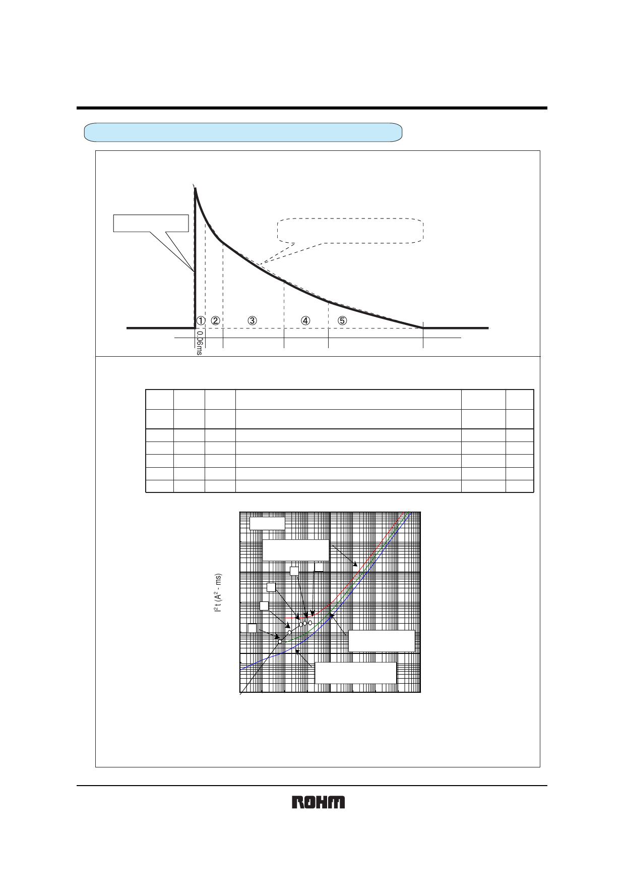
Joule Integral Calculation of Irregularly Increasing or Decreasing Current
Current mode: Irregular wave form + triangular wave form
Model: ICP-S1.2
Wave form:
10A
Actual wave form
8A
6A
Approximation curve for Joule
integral calculation
3.5A
2A
0.1ms 0.35ms
0.25ms
0.55ms
Wave form approximation: The above wave form (electric charge wave form) is approximated as an
irregular wave form to calculate the Joule integral of the wave form.
Test:
Item
Peak Segmented
current period
Joule integral
Accumu- Lapsed
lation time
No.
Im
(A)
t
(ms)
Formula
Coefficient × Im2 × t A2 • ms)
1 10 0.06 10×8×0.06+1/3×(10−8)2×0.06=
2
8 0.1 8×6×0.1+1/3×(8−6)2×0.1=
3
6 0.35 6×3.5×0.35+1/3×(6−3.5)2×0.35=
4 3.5 0.25 3.5×2×0.25+1/3×(3.5−2)2×0.25=
5
2 0.55 1/3×(2)2×0.55=
(A2 • ms) (ms)
4.88 4.88 0.06
4.93 9.81 0.16
8.07 17.88 0.51
1.93 19.81 0.76
0.73 20.54 1.31
Plotting test:
100000
Ta=25°C
10000
1000
A : Effective pulse breaking
line (with no margin)
4
5
3
100
2
10 1
B : Effective pulse critical
line (with no margin)
1
0.1
0.001
C : Effective pulse recommended
line (with margin)
0.01 0.1
1
10 100 1000 10000 100000
Time (msec)
I2 t-t Characteristic Curve (ICP-S1.2)
Test results: The steady-state current is between lines B and A. Therefore, it is considered that the
ICP-S will deteriorate or break the current due to the repetitive pulses.
Rev.A 10/13
Share Link: 