ILC6376 データシートの表示(PDF) - Fairchild Semiconductor
部品番号
コンポーネント説明
メーカー
ILC6376 Datasheet PDF : 12 Pages
| |||
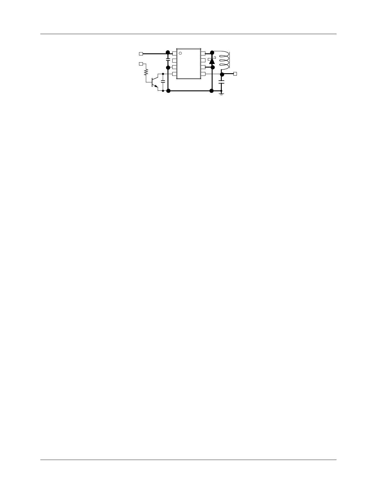
ILC6376/77
VIN
S/D
*CIN +
10µF
1
8
2 ILC6376/77 7
3
6
(TOP VIEW)
4
5
CSS
SD1
L
22µH
VOUT
+
CL
47µF
Fig 1. Typical step-down DC-DC
converter application
SD1: SS12 Schottky Diode (FAIRCHILD)
CL: 10V/47µF Tantalum Capacitor (NICHICON, F93)
CSS: 4700pF Ceramic Capacitor
CIN: 16V / 10µF Tantalum Capacitor (NICHICON, F93)
Figure 1 shows a typical fixed output voltage step-down DC-DC
converter application circuit for ILC6376/77SOXX.
External component selection
Proper selection of external components is important for
achieving high performance. The output inductor selected
should have low DC resistance on the order of 0.2Ω or less
and saturation current rating of 1A or higher. Recommended
inductors are Sumida CD54 (22µH, 0.18Ω max DC resis-
tance) or Coilcraft DO3308P-223 (22µH, 0.18Ω max DC
resistance) or equivalent.
The catch diode should be a schottky diode with low forward
drop and rated at 1A or greater current, SS12 or it’s equiva-
lent is recommended.
Input and output capacitors should be tantalum capacitors
with low equivalent series resistance (ESR) and voltage rat-
ing higher than the actual application.
Soft-start
Pin 4 of ILC6376/77 functions as the soft-start pin as well as
the shutdown pin. A soft-start capacitor (from pin 4 to
ground) controls the rate at which the power supply starts up;
thus preventing large overshoots at the output as well as
large in-rush current. The value for CSS should be 100pF or
greater.
Shutdown
The ILC6376/77 is placed in shutdown mode by taking pin 4
to ground. In shutdown, the quiescent current of the device is
under 2µA. When using the shutdown feature, pin 4 must be
driven from an open collector or open drain output without
employing an external pull-up resistor, as shown in figure 2.
Over-current and short-circuit protection
In the event of an over-current or short-circuit condition, the
ILC6376/77 cycles the soft-start pin in a hiccup mode to pro-
vide fault protection. When the output voltage decreases due
to overload, the ILC6376/77 will operate continuously at the
maximum duty cycle. If the period of maximum duty cycle
operation exceeds TPRO (typically 5 msec), pin 4 will be
pulled low; thus discharging the external soft-start capacitor
CSS. This action inhibits the regulator’s PWM action. Next,
the ILC6376/77’s soft-start circuitry starts recharging CSS
and initiates a controlled start-up. If the overload condition
continues to exist, the above sequence of events will repeat;
thus continuing to cycle the soft-start function.
Note that very little power is dissipated with this method of
fault protection versus constant current limit protection.
Even though the internal power MOSFET is pulsed on and
off at high peak current, the DC current is low; thus leading
to low power dissipation even under short-circuit conditions.
Keep in mind that the duration of maximum duty cycle
condition is used to trigger the ILC6376/77’s fault protec-
tion circuit. As such, a small input-output (VIN - VOUT)
differential voltage may trigger the device’s fault protec-
tion circuitry even at low output current.
Undervoltage Lockout
The undervoltage lockout feature prevents faulty operation
by disabling the operation of the regulator when input volt-
age is below the minimum operating voltage, VUVLO.
When the input voltage is lower than VUVLO the device
disables the internal P-channel MOSFET and provides
“high” output at both EXT1 and EXT2 outputs.
©2001 Fairchild Semiconductor Corporation
6
Share Link: 