IR2157 データシートの表示(PDF) - International Rectifier
部品番号
コンポーネント説明
メーカー
IR2157 Datasheet PDF : 20 Pages
| |||
IR2157
ADVANCED INFORMATION
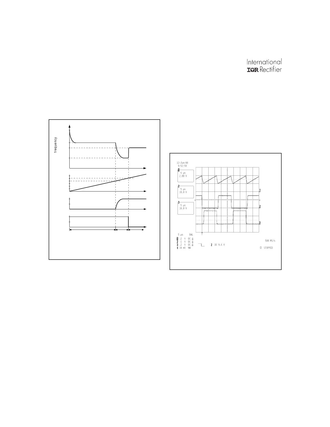
The Control Sequence & Timing
Component Selection
The IR2157 uses the following control sequence
(Figure 3) to drive rapid start fluorescent lamps.
fStart
fPH
fRun
fmin
t
5V
VCPH
The heart of this controller is an oscillator which
resembles those found in many popular PWM voltage
regulator ICs. In its simplest form, this oscillator
consists of a timing resistor and capacitor connected
to ground. The voltage across the timing capacitor
CT is a sawtooth, where the rising portion of the ramp
is determined by the current in the RT pin, and the
falling portion of the ramp is determined by an external
deadtime resistor RDT. The oscillograph in Figure 4
illustrates the relationship between the oscillator
capacitor waveform and the gate driver outputs.
2V
VRPH
2V
VRUN
Preheat mode
Ignition Run mode
Ramp
mode
Figure 3: IR2157 control sequence
The control sequence used in the IR2157 allows
the Run Mode operating frequency of the ballast to
be higher than the ignition frequency (i.e., fstart >
fph > frun > fign). This control sequence is
recommended for lamp types where the ignition
frequency is too close to the run frequency to ensure
proper lamp striking for all production resonant LC
component tolerances (please note that it is possible
to use the IR2157 in systems where fstart > fph >
fign > frun, simply by leaving the RUN pin open).
Six pins in the IC are used to control the Startup,
Preheat, Ignition Ramp, and Run modes of
operation, and to allow ballast and lamp engineers
the flexibility to optimize their designs for virtually
any lamp type.
Figure 4
The deadtime can be programmed by means of the
external RDT resistor, given a certain range of CT
capacitor values, using the graph shown in Figure 5.
The RT input is a voltage-controlled current source,
where the voltage is regulated to be approximately
2.0V. In order to maintain proper linearity between
the RT pin current and the CT capacitor charging
current, the value of the RT pin current should be
kept between 50µA and 500µA. The RT pin can
also be used as a feedback point for closed loop
control.
10
Share Link: 