IR1169S データシートの表示(PDF) - International Rectifier
部品番号
コンポーネント説明
メーカー
IR1169S Datasheet PDF : 28 Pages
| |||
IR1169S
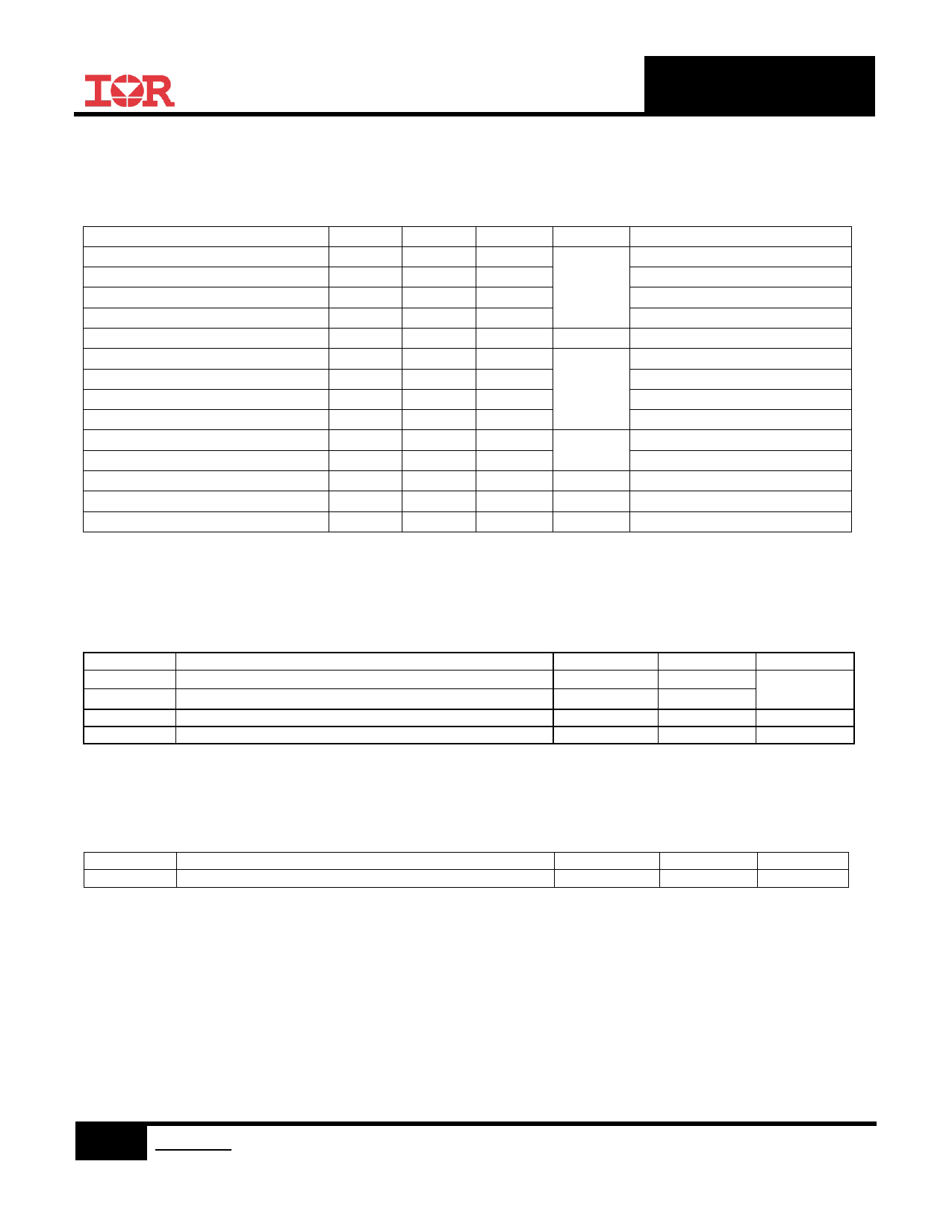
Absolute Maximum Ratings
Absolute maximum ratings indicate sustained limits beyond which damage to the device may occur. All voltage
parameters are absolute voltages referenced to COM, all currents are defined positive into any lead. The thermal
resistance and power dissipation ratings are measured under board mounted and still air conditions.
Parameters
Symbol Min.
Max.
Units
Supply Voltage
Enable Voltage
Cont. SYNC Voltage
Pulse SYNC Voltage
VCC
-0.3
20
VEN
-0.3
20
V
VSYNC
-0.3
20
VSYNC
-0.7 †
20
SYNC Current
Cont. Drain Sense Voltage
Pulse Drain Sense Voltage
Source Sense Voltage
ISYNC
-10
10
mA
VD
-1
200
VD
-5
200
V
VS
-3
20
Gate Voltage
Operating Junction Temperature
Storage Temperature
Thermal Resistance
Package Power Dissipation
VGATE
TJ
TS
RJA
PD
-0.3
-40
-55
20
150
°C
150
128
°C/W
970
mW
Switching Frequency
fsw
500
kHz
† An input resistor of 2kΩ or above is required to SYNC pin for negative pulse
Remarks
VCC=20V, Gate off
SOIC-8
SOIC-8, TAMB=25°C
Recommended Operating Conditions
For proper operation the device should be used within the recommended conditions.
Symbol
Definition
VCC
Supply Voltage
VD
Drain Sense Voltage
TJ
Junction Temperature
Fsw
Switching Frequency
†† VD -3V negative spike width ≤100ns
Min.
11
††
-3
-25
---
Max.
19
200
125
500
Units
V
°C
kHz
Recommended Component Values
Symbol
RMOT
Component
MOT pin resistor value
Min.
5
Max.
75
Units
k
5 www.irf.com © 2013 International Rectifier
Nov 6, 2013
Share Link: 