NX25F080A-5TI-R データシートの表示(PDF) - NexFlash -> Winbond Electronics
部品番号
コンポーネント説明
メーカー
NX25F080A-5TI-R Datasheet PDF : 25 Pages
| |||
NX25F080A
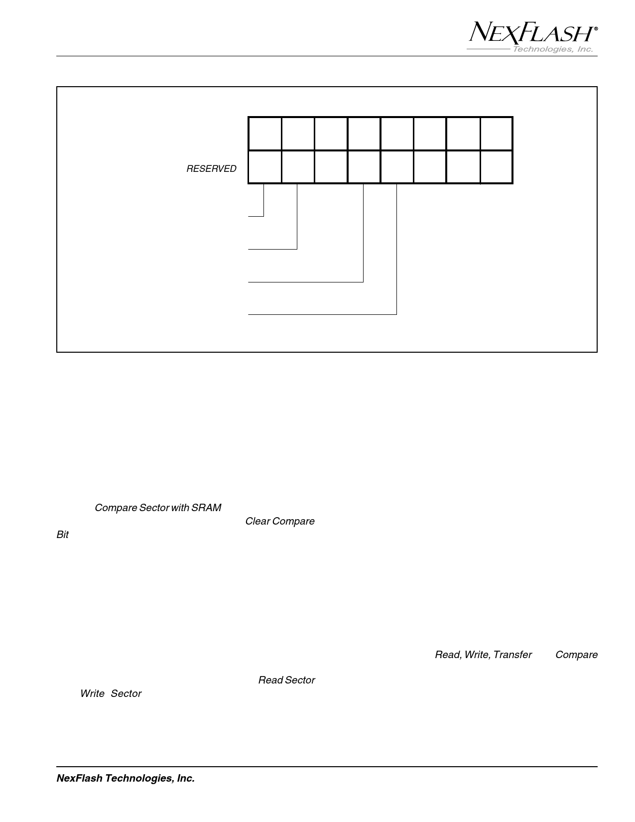
S7 S6 S5 S4 S3 S2 S1 S0
1
x =RESERVED Busy TR X WE CNE X X X
2
READ/BUSY
3
SRAM AND PROGRAM
BUFFER TRANSFER
FLASH ARRAY WRITE
ENABLE/DISABLE
4
SECTOR-SRAM
COMPARE NOT EQUAL
5
Figure 8. Status Register Bit Locations
6
Compare Not Equal, CNE
The CNE status bit is located at bit ST[3] of the Status
Register. The bit provides a cumulative comparison result
during a Compare Sector with SRAM command. The CNE
bit is reset to a 0 upon power-up or after a Clear Compare
Bit command is executed.
CNE = 1 Sector & SRAM contents are not equal.
CNE = 0 Sector & SRAM are equal or CNE bit reset.
Command Set
The NX25F080A has a powerful command set that is fully
controlled through the SPI bus. Command relations are
shown in Figure 5 and a list of commands and their
associated address, status, clock, and data bytes are
shown in Table 3. Detailed clock timing of the Read Sector
and Write Sector command sequences is shown in
Figures 10 and 11.
7
8 After power up, a device enters an idle state that will
maintain until CS pin is asserted low. All commands are
entered from the SPI serial data input (SI) pin on the rising
edge of SCK while CS is asserted low. All command,
9 address, and configuration bits are shifted into the device
with most-significant-bit-first. Data bits read from the
device are shifted out with least significant byte first
(i.e., byte-00H, byte-01H,...). The bit order within each
10 byte is most-significant-bit first (i.e.,D7,...D0). All com-
mands are completed by asserting the CS pin high.
Note that the entire 536-byte contents of a Flash sector, the
11 SRAM, or Program Buffer does not have to be
accessed all at once. Read, Write, Transfer, and Compare
commands allow for byte addressing. Thus a single byte,
or clocked sequence of bytes, can be accessed at any
12 starting location within the 536-byte boundary as specified
by the byte-address field.
NexFlash Technologies, Inc.
9
PRELIMINARY NXSF005C-0699
06/11/99 ©
Share Link: 