HTRC11001T データシートの表示(PDF) - Philips Electronics
部品番号
コンポーネント説明
メーカー
HTRC11001T Datasheet PDF : 20 Pages
| |||
Philips Semiconductors
HITAG reader chip
Product specification
HTRC11001T
8.6 Idle and Power-down mode
The HTRC11001T can be switched into the Idle mode via
setting bit PD = 1 and resetting bit PD_MODE = 0
(see Table 3). In this Idle mode, only the oscillator and a
few other system components are active.
It is also possible to switch the HTRC11001T completely
off. This is achieved by the Power-down mode (bit PD = 1
and bit PD_MODE = 1). Within this mode also the clock
oscillator is switched off. This reduces the supply current
of the HTRC11001T to less than 20 µA.
8.7 Serial interface
The communication between the HTRC11001T and the
microcontroller is done via a 3-wire digital interface. The
interface is operated by the following signals:
• Clock pulse on pin SCLK
• Data input on pin DIN
• Data output on pin DOUT.
Pins SCLK and DIN are realized as Schmitt-trigger inputs.
Pin DOUT is an open-drain output with an internal pull-up
resistor.
All commands transmitted to the HTRC11001T serial
interface start with the Most Significant Bit (MSB).
Input DIN and output DOUT are valid when pin SCLK is at
HIGH level.
8.7.2 GLITCH FILTER
Connecting pin MODE to VDD enables digital filtering of the
SCLK and the DIN input signals. This mode offers
improved immunity against noise and interference
(glitches) on these interface signals. It is intended to be
used in the so called ‘active antenna applications’ where
the microcontroller and the reader communicate via long
signal lines (e.g. 1 meter).
In other applications pin MODE has to be connected to
ground (pin VSS).
For a detailed description of this feature, refer to the
application note “AN 98080 Read/Write devices based on
the HITAG Read/Write IC HTRC110”.
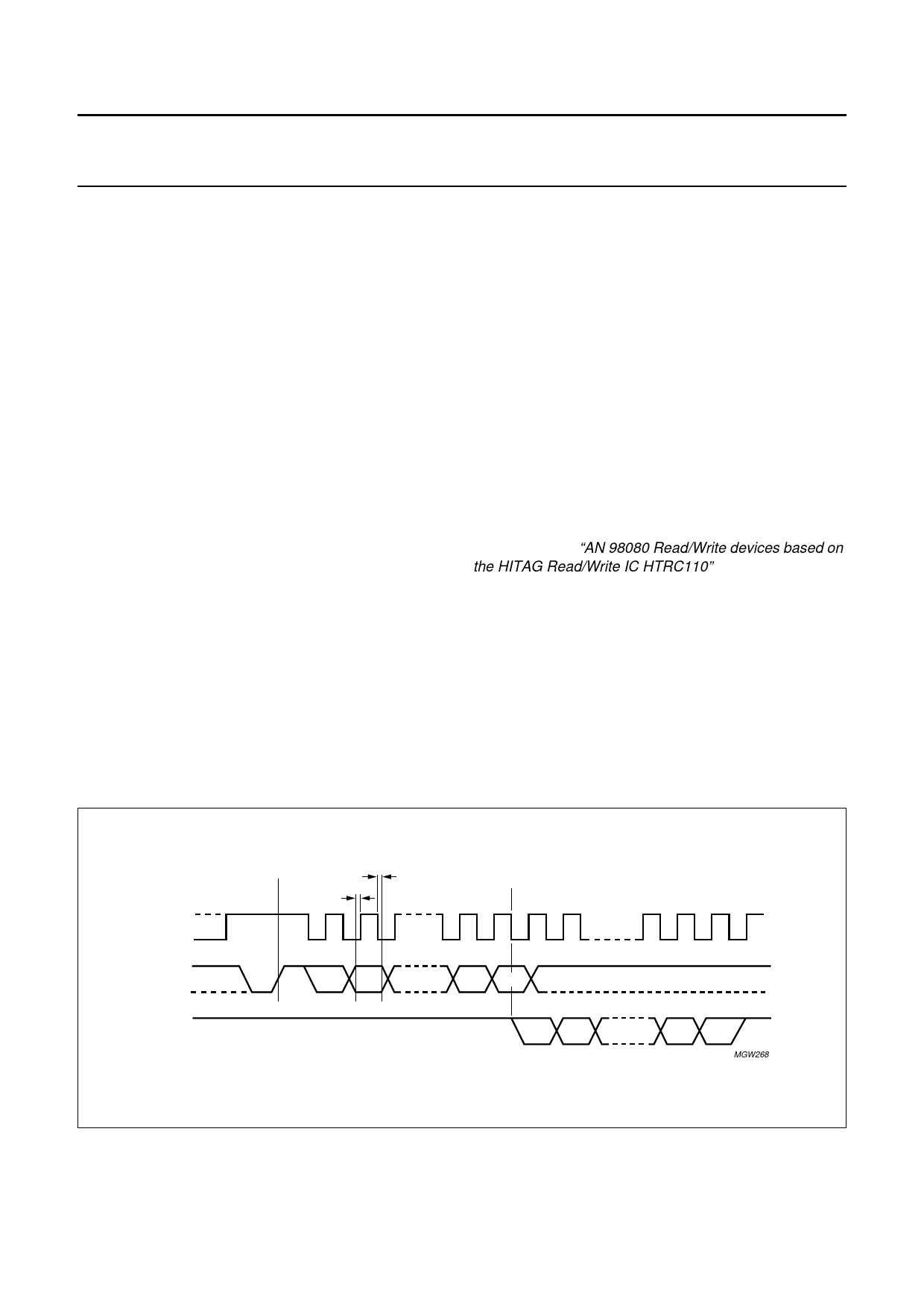
8.7.1 COMMUNICATION PROTOCOL
Every communication between the HTRC11001T and the
microcontroller begins with an initialization of the serial
interface. The interface initialization condition is a
LOW-to-HIGH transition on pin DIN while pin SCLK is at
HIGH level (see Fig.3).
handbook, full pagewidth
SCLK
DIN
DOUT
initialization
th
t su
D7 D6
D1 D0
D7 D6
Fig.3 Serial interface communication protocol.
D1 D0
MGW268
2001 Nov 23
7
Share Link: 