ISPLSI1016EA データシートの表示(PDF) - Lattice Semiconductor
部品番号
コンポーネント説明
メーカー
ISPLSI1016EA Datasheet PDF : 13 Pages
| |||
Specifications ispLSI 1016EA
Boundary Scan
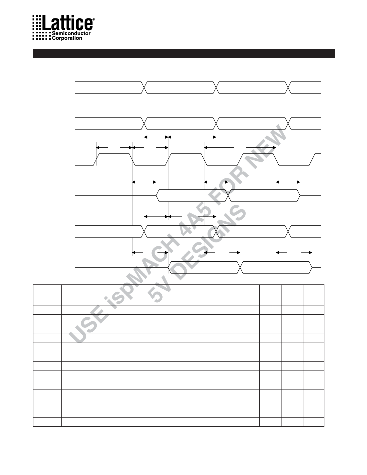
Figure 2. Boundary Scan Waveforms and Timing Specifications
TMS
TDI
TCK
Tbtch
Tbtsu
Tbtcl
Tbth
NEW Tbtcp
OR TDO
A5 F S Data to be
4 N captured
CH SIG Data to be
E driven out
Tbtvo
Tbtco
Valid Data
Tbtcpsu
Tbtcph
Data Captured
Tbtuov
Tbtuco
Valid Data
MA D Symbol
isp 5V tbtcp
tbtch
tbtcl
E tbtsu
US tbth
Parameter
TCK [BSCAN test] clock pulse width
TCK [BSCAN test] pulse width high
TCK [BSCAN test] pulse width low
TCK [BSCAN test] setup time
TCK [BSCAN test] hold time
Tbtoz
Valid Data
Tbtuoz
Valid Data
Min Max
100 –
50
–
50
–
20
–
25
–
Units
ns
ns
ns
ns
ns
trf
TCK [BSCAN test] rise and fall time
50
– mV/ns
tbtco
TAP controller falling edge of clock to valid output
–
25 ns
tbtoz
TAP controller falling edge of clock to data output disable
–
25 ns
tbtvo
TAP controller falling edge of clock to data output enable
–
25 ns
tbtcpsu BSCAN test Capture register setup time
40
–
ns
tbtcph BSCAN test Capture register hold time
25
–
ns
tbtuco BSCAN test Update reg, falling edge of clock to valid output
–
50 ns
tbtuoz BSCAN test Update reg, falling edge of clock to output disable
–
50 ns
tbtuov BSCAN test Update reg, falling edge of clock to output enable
–
50 ns
3
Share Link: 