KA8328 データシートの表示(PDF) - Fairchild Semiconductor
部品番号
コンポーネント説明
メーカー
KA8328 Datasheet PDF : 15 Pages
| |||
KA8328D
VCR PRODUCTS
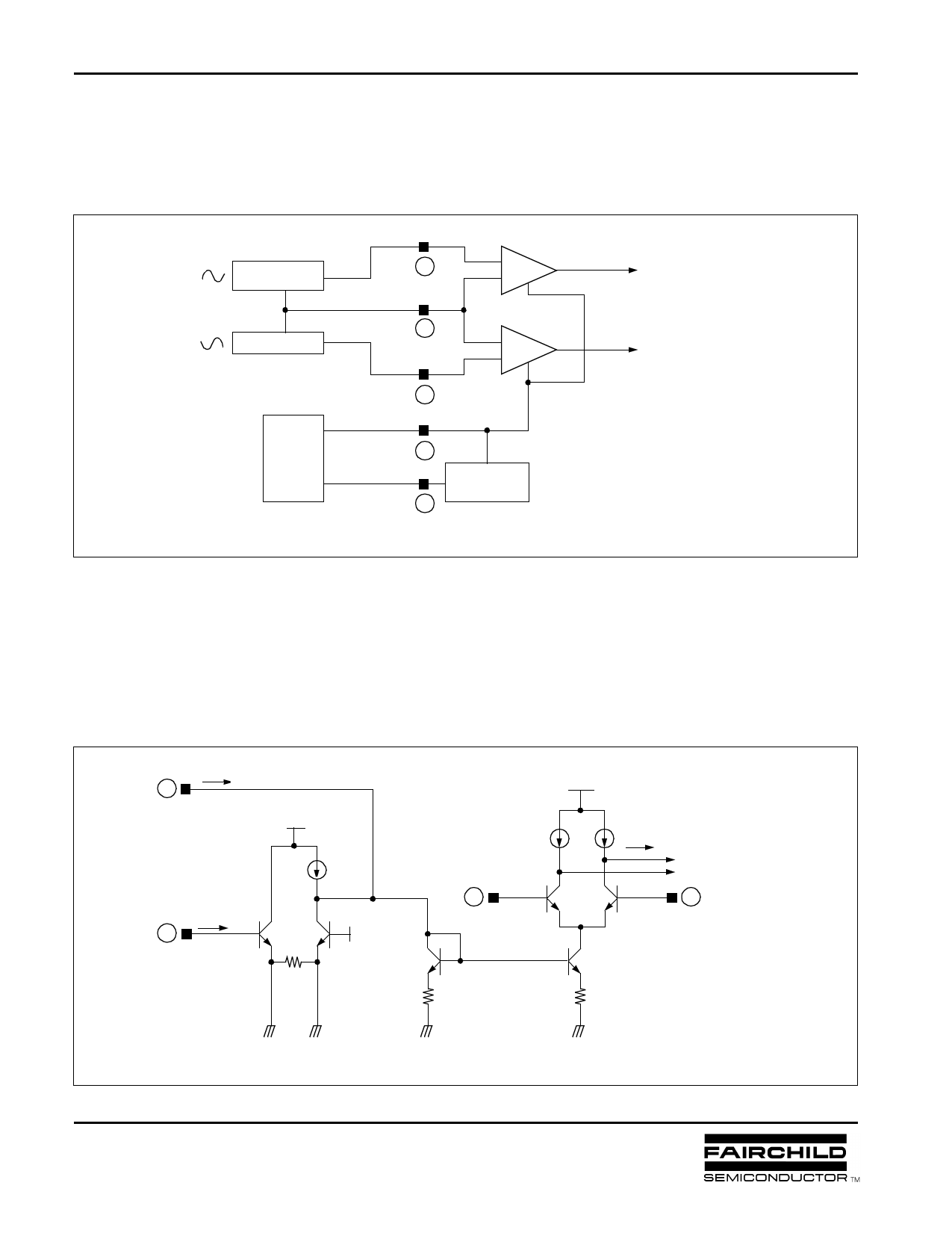
4.With having the output signal of the hall sensor which detects the rotor position and the servo current (or voltage)
which controls the output current as in the following diagram, the differential amplifiers in the hall input parts are
operated so that the current may flow at a proper phase of the motor.
Motor
A phase signal
Hall sensor
Hall sensor
Motor
B phase signal
Servo
Circuit
ICTL
VCTL
Hall input
7
IN1
Hall input
8
IN2
9
2
V-I
Converter
3
AMP
(For motor A phase)
AMP
(For motor B phase)
<Input part diagram>
The followings is the simplified circuit diagram of the input part circuit. Firstly when the input control current (ICTL)
is inputted, TR Q5 is operated, and TR Q3 or TR Q4 of the differential amplifier is operated in accordance with
the output signal of the Hall sensor, and so the current (I1) is outputted.
Next when the input control voltage (VCTL) is inputted, if the input voltage is higher than the standard voltage
(VREF, 2.3V), TR Q1 is operated, and so TR Q5 is operated by the current source (IS).
ICTL
2
VCTL
3
VREG
IS
Q1 Q2
VREF
VREG
I1
AMP
(For motor A phase)
7
Q3 Q4
8
Q5
* The differential amplifier
is described about IN1 only.
<Input part circuit>
8
MIC-99D001
January 1999
Share Link: 