KS0066 データシートの表示(PDF) - Samsung
部品番号
コンポーネント説明
メーカー
KS0066 Datasheet PDF : 33 Pages
| |||
KS0066U
16COM / 40SEG DRIVER & CONTROLLER FOR DOT MATRIX LCD
PIN DESCRIPTION
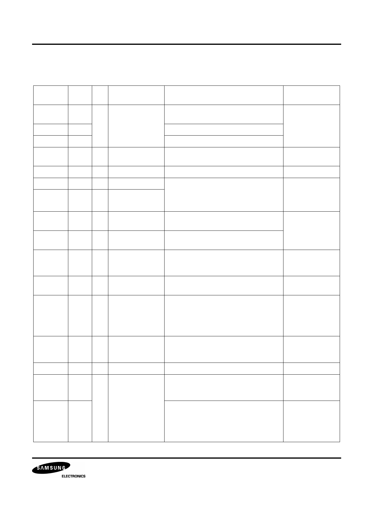
Table 2. Pin Description
Pin
VDD
Pin
No.
33
GND
V1-V5
S1-S40
C1-C16
OSC1
OSC2
23
26-30
1-22,
63-80
47-62
24
25
CLK1
31
CLK2
32
M
34
D
35
RS
36
R/W
37
E
38
DB0-DB3 39-42
DB4-DB7 43-46
I/O
Name
- Supply Voltage
O Segment output
Description
Supply Voltage for logical circuit
(+3V ± 10%,+5V ± 10%)
Ground (0V)
Bias voltage level for LCD driving
Segment signal output for LCD drive
Interface
Power Supply
LCD
O Common output Common signal output for LCD drive
LCD
I Oscillator
O Oscillator
Oscillator. When using internal oscillator,
connect external Rf resistor.
If external clock is used, connect it to
OSC1.
External
resistor/oscillator
(OSC1)
O Extension driver
Latch clock
Extension driver latch clock
Extension driver
O Extension driver
Shift clock
Extension driver shift clock
O Alternated signal
for LCD driver
output
Outputs the alternating signal to convert
LCD driver waveform to AC.
Extension driver
O Display data
interface
Outputs extension driver data
(the 41st dot's data)
Extension driver
I Register select
Used as register selection input.
When RS = “High”, Data register is
selected.
When RS = “Low”, Instruction register is
selected.
MPU
I Read/Write
Used as read/write selection input.
When RW = “High”, read operation.
When RW = “Low”, write operation.
MPU
I Read/Write enable Used as read/write enable signal.
MPU
I/O Data bus 0-7
In 8-bit bus mode, used as low order
bidirectional data bus.
In 4-bit bus mode, open these pins.
MPU
In 8-bit bus mode, used as high order
bidirectional data bus.
In 4-bit bus mode, used as both high and
low order.
DB7 used for Busy Flag output.
MPU
Share Link: 