L4964 データシートの表示(PDF) - STMicroelectronics
部品番号
コンポーネント説明
メーカー
L4964 Datasheet PDF : 13 Pages
| |||
L4964
APPLICATION INFORMATION
CHOOSING THE INDUCTOR AND CAPACITOR
The input and output capacitors of the L4964 must
have a low ESR and low inductance at high current
ripple.
Preferably, the inductor should be a toroidal type or
wound on a Moly-Permalloy nucleus.Saturation
must not occur at current levels below 1.5 times the
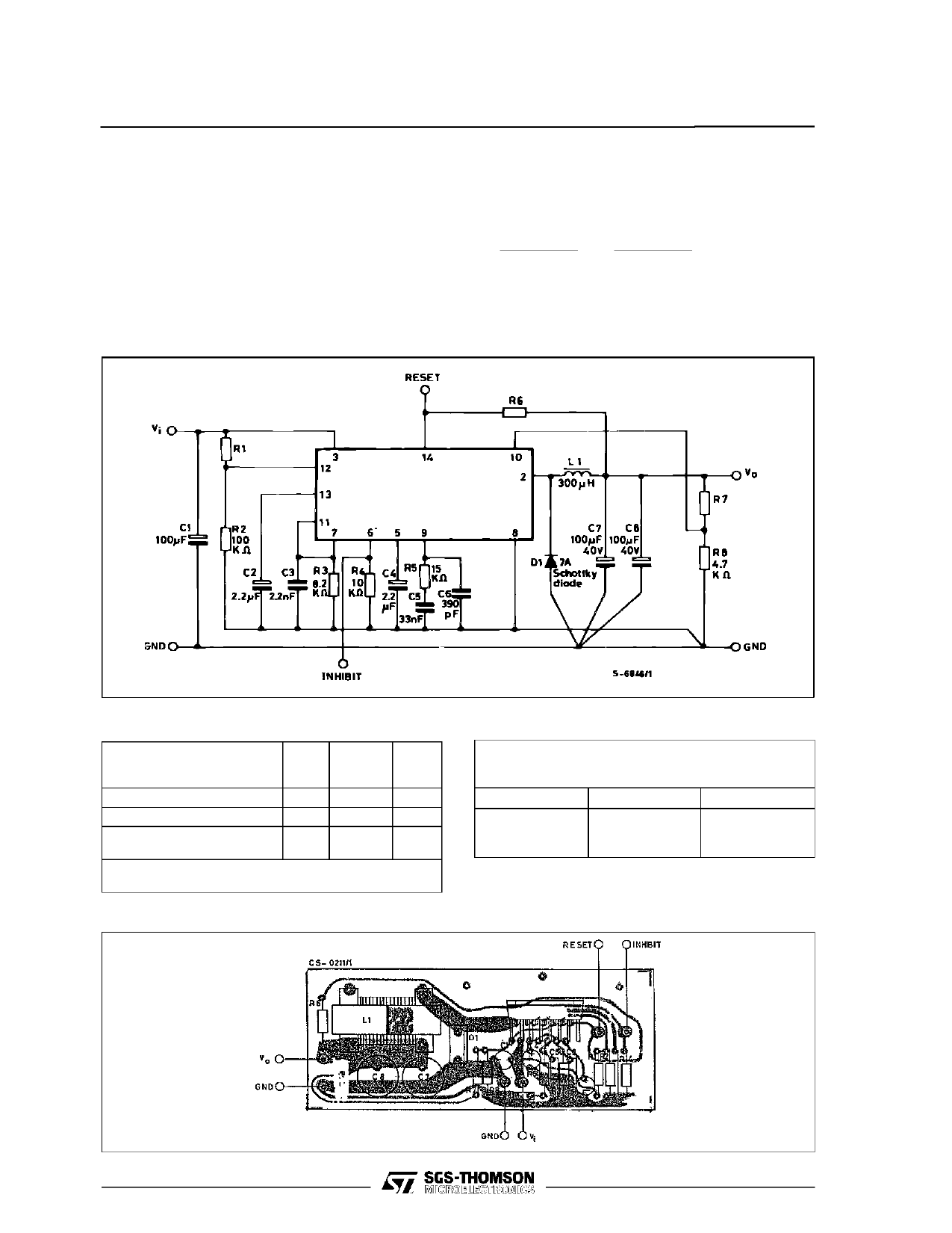
Figure 13 : Typical Application Circuit.
current limiter level. MPP nuclei have very soft satu-
ration characteristics.
L
=
(Vi −
Vi
Vo) V0
f ∆IL
,
C
=
(Vi − Vo) V0
8L f2 ∆Vo
∆IL = Inductance current ripple
∆Vo = Output ripple voltage
L 4964
C7, C8 : EKR (ROE)
SUGGESTED INDUCTOR (L1)
Core Type
No
Turns
Wire
Gauge
(mmm)
Magnetics 58930 – A2MPP 43
1.0
Thomson GUP 20 x 16 x 7 50
0.8
Siemens EC 35/17/10
(B6633& – G0500 – X127)
40 2 x 0.8
VOGT 250 µH Toroidal Coil, Part Number
5730501800
Air
Gap
(mm)
–
0.7
–
Resistor Values for Standard Output Volt-
ages
V0
12 V
15 V
18 V
R8
4.7 kΩ
4.7 kΩ
4.7 kΩ
R7
6.2 kΩ
9.1 kΩ
12 kΩ
Figure 14 : P.C. Board and Component Layout of the Circuit of Fig. 13 (1:1 scale)
10/13
Share Link: 