LB1695 データシートの表示(PDF) - SANYO -> Panasonic
部品番号
コンポーネント説明
メーカー
LB1695 Datasheet PDF : 7 Pages
| |||
LB1695
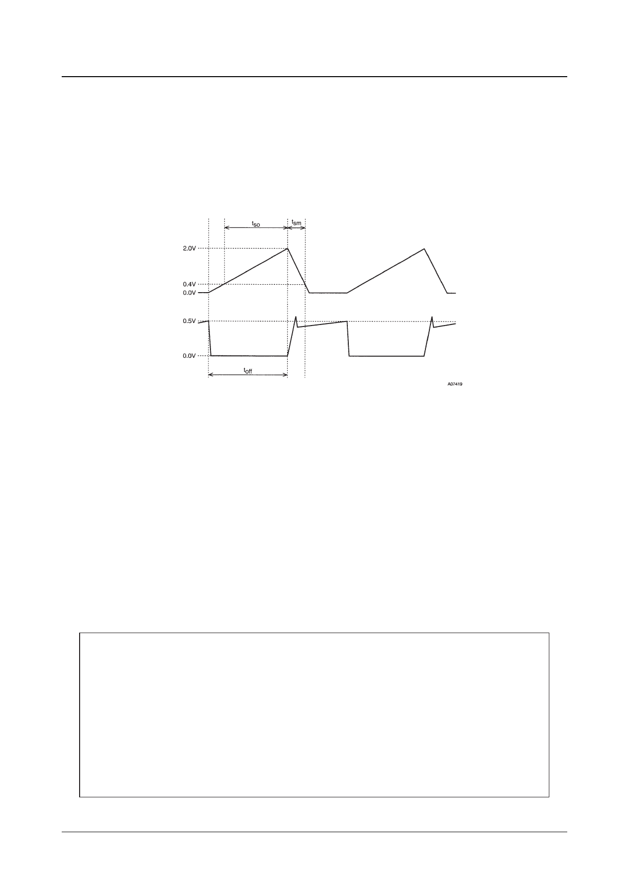
(1) If a shorter output off time is used:
Since the output off time and the output current ignored time are set to have a ratio of about 3:1 by IC internal circuits, it
is not possible to set these periods independently. Thus the output current ignored period may become insufficient if the
output off time is set to an excessively short period. If the output current ignored period is too short, the reverse current
in the regenerative current absorption external diode may cause the current limiter circuit to operate. (See Section 7.2.)
Also, if the output off time is decreased, the diode reverse current will increase and ASO may become a problem.
(2) If a longer output off time is used:
If an excessively long output off time is used, the average current will decrease resulting in reduced torque during
motor startup. For some motor types, this may make it impossible to switch from the current limiter operating state
to steady state operation.
C pin voltage
RF pin voltage
Figure 1. Current Limiter Operating Waveforms
8.IC internal power dissipation calculation
Pd = (VCC × ICC) + (VM × IM) – (power dissipated in the motor coils)
9.Techniques for measuring IC internal temperature increases
Since it is not possible to measure the IC internal temperature directly, one of the following techniques is normally
used for temperature measurement.
9.1 Thermocouple measurement
When using a thermocouple for temperature measurement, the thermocouple is attached to a fin on the heat sink.
While this measurement technique is simple, it suffers from large measurement errors when the thermal generation
process is not at steady state.
9.2 Measurement using IC internal diode properties
We recommend using the properties of the parasitic diode that exists between FG1 and ground for measuring the
temperature of this IC. Set FG1 to the high (off) state and measure the VF voltage of the parasitic diode. Then
calculate the temperature from the temperature characteristics of the VF voltage.
s No products described or contained herein are intended for use in surgical implants, life-support systems, aerospace
equipment, nuclear power control systems, vehicles, disaster/crime-prevention equipment and the like, the failure of
which may directly or indirectly cause injury, death or property loss.
s Anyone purchasing any products described or contained herein for an above-mentioned use shall:
Accept full responsibility and indemnify and defend SANYO ELECTRIC CO., LTD., its affiliates, subsidiaries and
distributors and all their officers and employees, jointly and severally, against any and all claims and litigation and all
damages, cost and expenses associated with such use:
Not impose any responsibility for any fault or negligence which may be cited in any such claim or litigation on
SANYO ELECTRIC CO., LTD., its affiliates, subsidiaries and distributors or any of their officers and employees
jointly or severally.
s Information (including circuit diagrams and circuit parameters) herein is for example only; it is not guaranteed for
volume production. SANYO believes information herein is accurate and reliable, but no guarantees are made or implied
regarding its use or any infringements of intellectual property rights or other rights of third parties.
This catalog provides information as of June, 1997. Specifications and information herein are subject to change
without notice.
No. 5678-7/7
Share Link: 