LB1980JH データシートの表示(PDF) - SANYO -> Panasonic
部品番号
コンポーネント説明
メーカー
LB1980JH Datasheet PDF : 7 Pages
| |||
LB1980JH
Continued from preceding page.
Pin No. Pin Name
Function
11
CTL
Speed control input. The control implemented is fixed
current drive controlled by current feedback from Rf.
Gm=0.58 / V (typical) when Rf=0.5W
12
CTLREF Control reference voltage. While this pin is set to about
0.43×VCC internally, this voltage can be modified by
applying a voltage from a low-impedance circuit.
(The input impedance is about 4.3kΩ).
13
LIM
Current limiter function control. The output current can be
varied linearly by applying a voltage to this pin.
The slope is 0.5A / V (typical) when Rf=0.5Ω.
15
UIN+
U phase Hall element inputs.
16
UIN-
Logic high is defined as states where IN+>IN-.
17
VIN+
V phase Hall element inputs.
18
VIN-
Logic high is defined as states where IN+>IN-.
19
WIN+
W phase Hall element inputs.
20
WIN-
Logic high is defined as states where IN+>IN-.
21
VCC
Power supply for all internal blocks other than the output
block. This voltage must be stabilized so that noise and
ripple do not enter the IC.
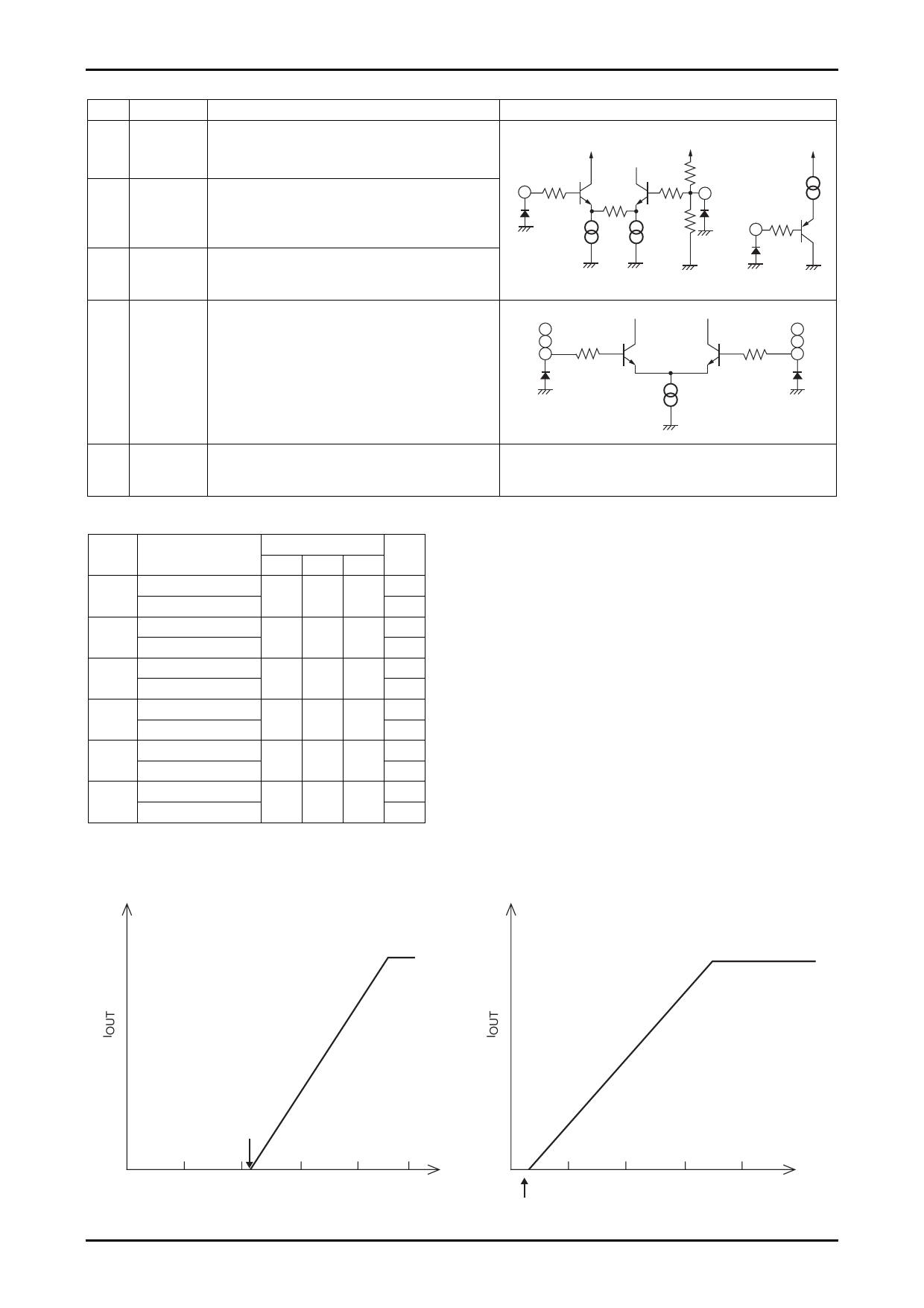
Equivalent circuit
CTL
11
200Ω
VCC
100µA
VCC
VCC
200Ω
7.5kΩ
10kΩ
12 CTLREF
200µA
max
LIM
13
200Ω
(+) input
15
17
19
200Ω
100µA
200Ω
(--) input
16
18
20
Truth Table and Control Functions
Source → Sink
Hall input
FR
U
V
W
Phase V → Phase W
H
1
H
H
L
Phase W → Phase V
L
Phase U → Phase W
H
2
H
L
L
Phase W → Phase U
L
Phase U → Phase V
H
3
H
L
H
Phase V → Phase U
L
Note: In the FR column, “H” refers to a voltage of
2.75V or higher, and “L” refers to 2.25V or
lower (when VCC=5V.)
Note: In the Hall input column, “H” refers to the state
in the corresponding phase where the +input is
at a potential at least 0.01V higher than the
-input, and “L” refers to the state where the
-input is at a potential at least 0.01V higher than
the +input.
Phase W → Phase V
H
4
L
L
H
Phase V → Phase W
L
Phase W → Phase U
H
5
L
H
H
Phase U → Phase W
L
Phase V → Phase U
H
6
L
H
L
Phase U → Phase V
L
Note: Since the drive technique adopted is a 180° technique, phases other than the sink and source phase do not turn off.
Control Function and Current Limiter Function
VLIM=5V
CTLREF: OPEN
VCTL=5V
CTLREF: OPEN
Gm1=0.58A / V typ
2.10V typ
0
1
2
3
4
5
VCTL
Control Characteristics
Slope: 0.50A / V typ
0
1
2
3
4
200mA / V typ
VLIM
Control Limiter Characteristics
No.A0231-6/7
Share Link: 