LC78631 データシートの表示(PDF) - SANYO -> Panasonic
部品番号
コンポーネント説明
メーカー
LC78631 Datasheet PDF : 34 Pages
| |||
LC78631E
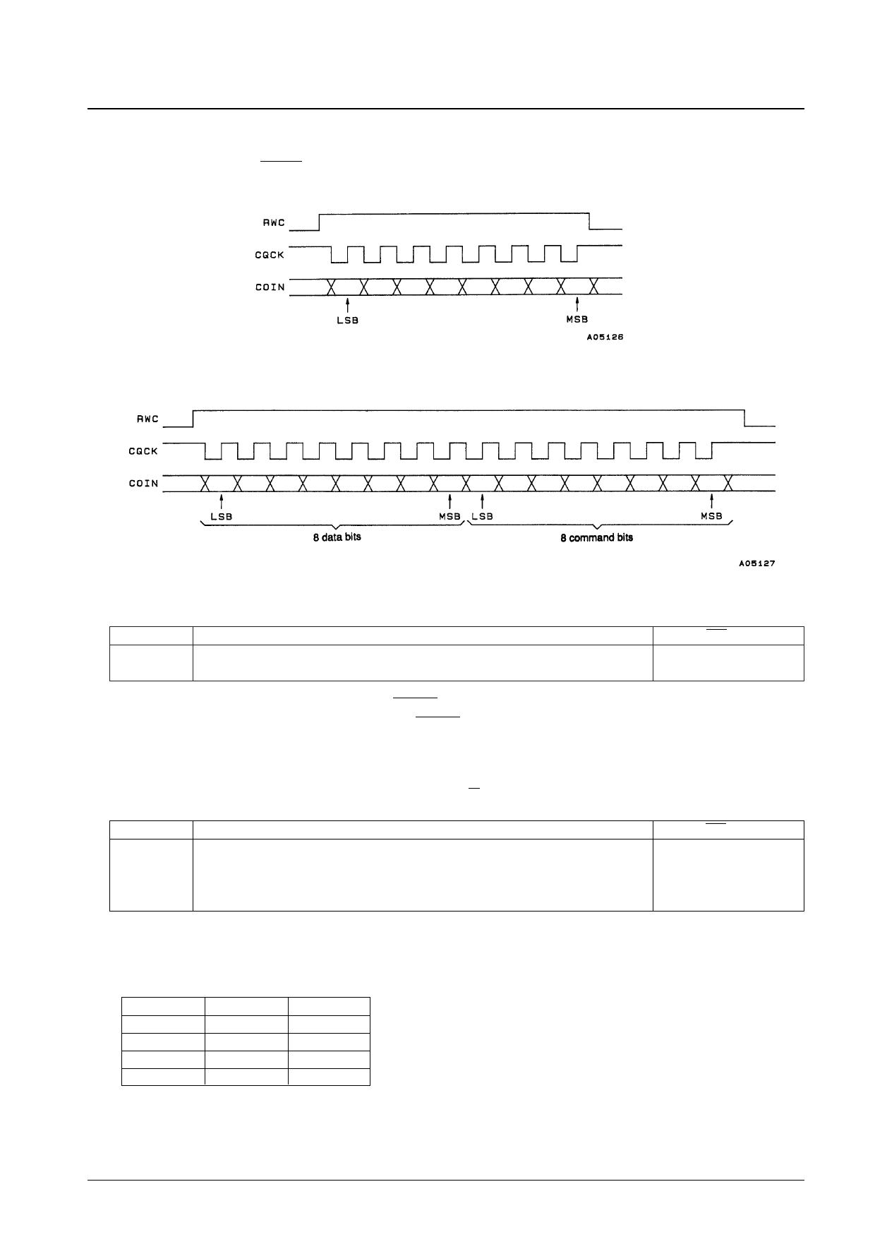
4. Command input
An external controller can execute LC78631E instructions by setting RWC high and inputting commands to COIN in
synchronization with the CQCK clock. Commands are executed on the fall of the RWC signal.
• Single-byte commands
• Two-byte commands
• Command noise reduction
Code
$EF
$EE
Command
COMMAND INPUT NOISE REDUCTION MODE
CLEAR THE ABOVE MODE
RES = low
q
This command can reduce the noise on the CQCK clock signal. While this is effective for noise pulses under
500 ns, the use of this function requires that the CQCK timings tWL, tWH, and tSU (see Figure 1 and 2) be set to
1 µs or longer.
5. CLV servo circuit
• CLV servo circuit; Pin 13: CLV+, pin 14: CLV–, pin 15: V/P
Code
$04
$05
$06
$07
Command
DISC MOTOR START (accelerate)
DISC MOTOR CLV (CLV)
DISC MOTOR BRAKE (decelerate)
DISC MOTOR STOP (stop)
RES = low
q
The CLV+ signal causes the disc to accelerate in the forward direction, and CLV– causes the disc to decelerate. The
microcontroller can select one of four modes: accelerate, decelerate, CLV, and stop. The table below lists the states
of the CLV+ and CLV– pins in each of these modes.
Mode
Accelerate
Decelerate
CLV
Stop
CLV+
High
Low
Pulse output
Low
CLV–
Low
High
Pulse output
Low
Note: The CLV servo control commands only set the TOFF pin low during CLV mode. That pin will be at the high
level at all other times. Thus controlling the TOFF pin with microcontroller commands is only possible in
CLV mode.
No. 5342-11/34
Share Link: 