LH1510AAB(2004) データシートの表示(PDF) - Vishay Semiconductors
部品番号
コンポーネント説明
メーカー
LH1510AAB Datasheet PDF : 10 Pages
| |||
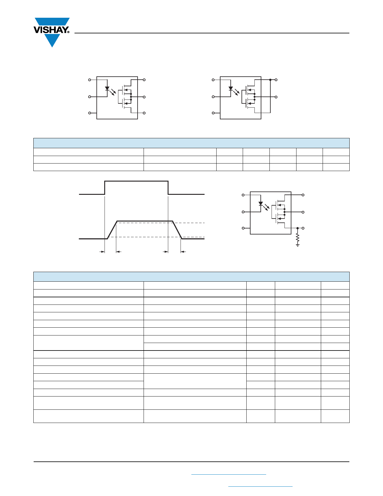
LH1510AAB/ AABTR/ AT
Vishay Semiconductors
Parameter
Output capacitance Pin 4 to 6
Switch offset
Test condition
IF = 0 mA, VL = 1.0 V
IF = 0 mA, VL = 50 V
IF = 5.0 mA
Symbol
Min
Typ.
Max
Unit
CO
27.75
pF
CO
10.82
pF
VOS
0.17
µV
Transfer
Parameter
Capacitance (input-output)
Turn-on time
Turn-off time
Test condition
VISO = 1.0 V
IF = 5.0 mA, IL = 50 mA
IF = 5.0 mA, IL = 50 mA
Symbol
Min
Typ.
Max
Unit
CIO
0.72
pF
ton
0.5
2.0
ms
toff
0.7
2.0
ms
Typical Characteristics (Tamb = 25 °C unless otherwise specified)
200
160
120
IFon=
80 5.0 to 20 mA
IFon=2.0 mA
IFon=3.0 mA
40 IFon=2.0 mA
0
-40 -20 0
20 40
60
80
ilh1510at_00
Ambient Temperature (°C)
Figure 1. Recommended Operating Conditions
120
100
80
T=85°C
T=25°C
T=-40°C
60
40
20
0
0
0.5
1
1.5
2
ilh1510at_02
LED Forward Voltage (V)
Figure 3. LED Forward Current vs. LED Forward Voltage
1.6
IF=50mA
1.5
IF=20mA
IF=10mA
1.4
1.3
1.2
IF=1mA
1.1 IF=2mA
IF=5mA
1
-40 -20 0 20 40 60 80
ilh1510at_01
Temperature (°C)
Figure 2. LED Voltage vs. Temperature
10
8
6
T=-40°C
T=25°C
T=85°C
4
2
0
0
16
32
48
64
80
ilh1510at_03
LED Reverse Voltage (V)
Figure 4. LED Reverse Current vs. LED Reverse Voltage
Document Number 83810
Rev. 1.3, 26-Oct-04
www.vishay.com
3
Share Link: 