SA8025ADK データシートの表示(PDF) - Philips Electronics
部品番号
コンポーネント説明
メーカー
SA8025ADK Datasheet PDF : 23 Pages
| |||
Philips Semiconductors
1.8GHz low-voltage Fractional-N synthesizer
Product specification
SA8025A
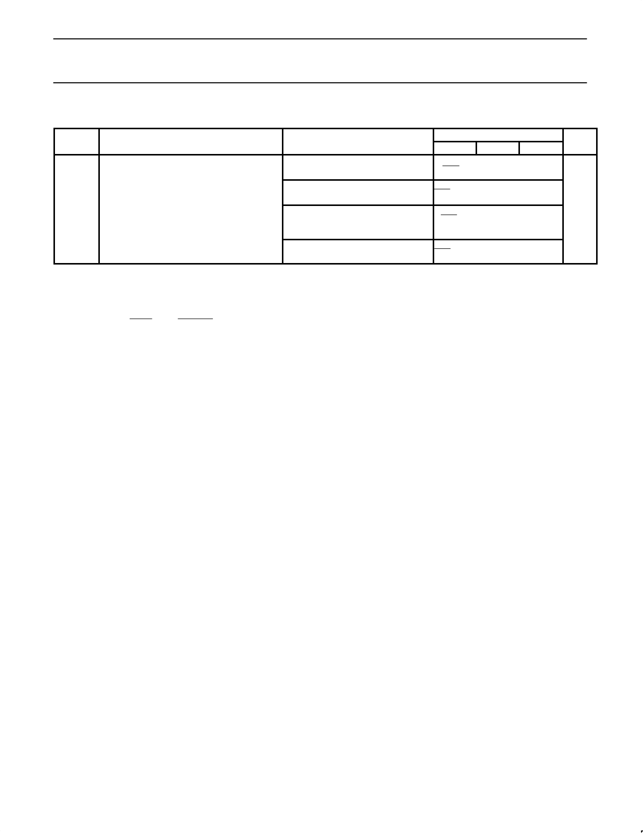
AC ELECTRICAL CHARACTERISTICS (Continued)
SYMBOL
PARAMETER
tSW Pulse width; STROBE
TEST CONDITIONS
A word, PR = ‘01’
A word, PR = ‘10’
A word, PR = ‘11’
A word, PR = ‘00’
LIMITS
UNITS
MIN
TYP
MAX
1
fVCO
@
(NM2
@ 65)
)
tW
1
fVCO
@
[(NM2
@
65)
)
(NM3
)
1)
@
68]
)
tW
1
fVCO
@
[(NM2
@
65
) (NM3 ) 1) @ 68
ns
) (NM4 ) 1) @ 73)] ) tW
1
fVCO
@
[(NM2
@
65)
)
(NM4
)
1)
@
73]
)
tW
NOTES:
1. When a serial input “A” word is programmed, the main charge pumps on PHP and PHI are in the “speed up mode” as long as STROBE = H.
When this is not the case, the main charge pumps are in the “normal mode”.
2. The relative output current variation is defined thus:
DIOUT
IOUT
+
2
@
(I2
|(I2
*
)
II11));|
with
V1
=
0.7V,
V2
=
VDDA
–
0.8V
(see
Figure
3).
3. FRD is the value of the 3 bit fractional accumulator.
4. Monotonicity is guaranteed with CN = 0 to 255.
5. Power supply current measured with fRF_IN = 1667.4MHz, NM1 = 0, NM2 = 1, NM3 = 1, NM4 = 4, FMOD = 8, N = 694 6/8, main phase
detector frequency = 2.4MHz, fREF IN = 19.2MHz, NR = 8, SM = 1, fAUX_IN = 150MHz, NA = 125, SA = 1, PA = 0, auxiliary phase detector
frequency = 300kHz, IRN = IRA = IRF = 25µA, CN = 160, CL = 0, CK = 0, lock condition, normal mode, VCCP = VDD = VDDA = 3V.
Operational supply current = IDDA + IDD + ICCP.
6. Specification condition: CN = 255
7. Specification conditions:
1) CN = 255; CL = 1, or
2) CN = 75; CL = 3
8. Typical output current | IPHI | = –IRN x CN x 2(CL+1) x CK/32:
1) CN = 160; CL = 3; CK = 1, or
2) CN = 160; CL = 2; CK = 2, or
3) CN = 160; CL = 1; CK = 4, or
4) CN = 160; CL = 0; CK = 8
9. Any RFD, CL = 1 for speed-up pump. The integral pump is intended for switching only and the fractional compensation is not guaranteed.
10. Specification conditions: FRD = 1 to 7; CL = 1.
11. Specification conditions:
1) FRD = 1 to 7; CL = 1; CK = 2, or
2) FRD = 1 to 7; CL = 2; CK = 1.
12. The matching is defined by the sum of the P and the N pump for a given output voltage.
13. Limited analog supply voltage range 4.5 to 5.5V.
14. For fIN < 50MHz, low frequency operation requires DC-coupling and a minimum input slew rate of 32V/µs.
15. Guaranteed by design.
16. FXTAL = 14.4MHz, VXTAL = 500mVP-P, comparison Freq. = 200kHz, Loop bandwidth = 5kHz, Audio filter = 300Hz to 15kHz.
1996 Oct 15
7
Share Link: 