LT1191 データシートの表示(PDF) - Linear Technology
部品番号
コンポーネント説明
メーカー
LT1191 Datasheet PDF : 12 Pages
| |||
LT1191
APPLICATIO S I FOR ATIO
Cable Terminations
The LT1191 operational amplifier has been optimized as a
low cost video cable driver. The ±50mA guaranteed output
current enables the LT1191 to easily deliver 7.5VP-P into
100Ω, while operating on ±5V supplies or 2.6VP-P on a
single 5V supply.
When driving a cable it is important to terminate the cable
to avoid unwanted reflections. This can be done in one of
two ways: single termination or double termination. With
single termination, the cable must be terminated at the
receiving end (75Ω to ground) to absorb unwanted en-
ergy. The best performance can be obtained by double
termination (75Ω in series with the output of the amplifier,
and 75Ω to ground at the other end of the cable). This
termination is preferred because reflected energy is ab-
sorbed at each end of the cable. When using the double
termination technique it is important to note that the signal
is attenuated by a factor of 2, or 6dB. This can be compen-
sated for by taking a gain of 2, or 6dB in the amplifier. The
cable driver has a –3dB bandwidth of 100MHz while
driving the 150Ω load. Note the response can be improved
by lowering the impedance of the feedback elements.
Double Terminated Cable Driver
5V
3+
7
6
75Ω CABLE
2
LT1191
–4
RG
–5V
RFB
75 Ω
Cable Driver Voltage Gain vs Frequency
10
AV = 2
RFB = 1k
RG = 330Ω
5
VS = ±5V
TA = 25°C
RFB= 1k
AV = 1 RG = 1k
0
RFB = 300Ω
RG = 300Ω
–5
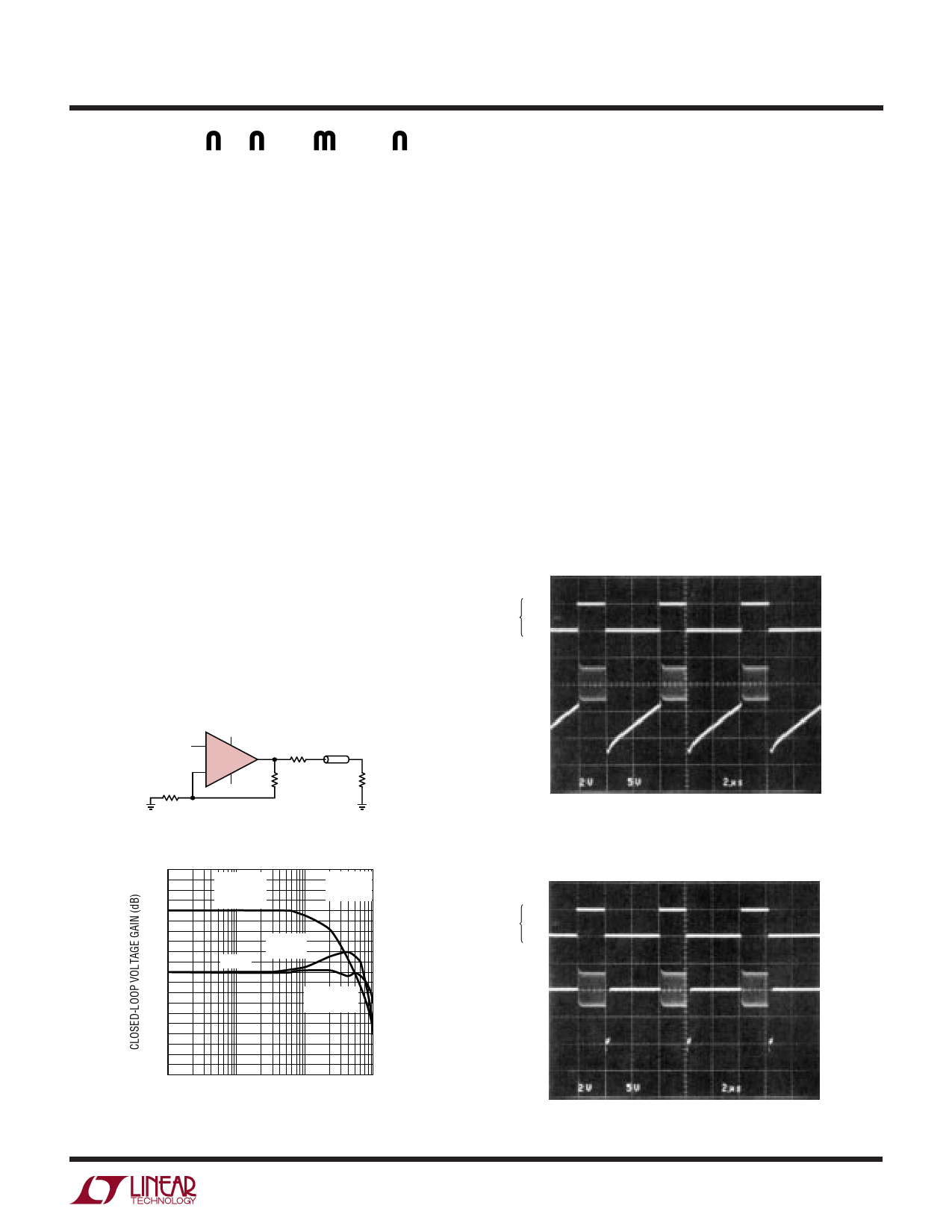
Using the Shutdown Feature
The LT1191 has a unique feature that allows the amplifier
to be shut down for conserving power or for multiplexing
several amplifiers onto a common cable. The amplifier will
shut down by taking Pin 5 to V–. In shutdown, the amplifier
dissipates 15mW while maintaining a true high impedance
output state of 15kΩ in parallel with the feedback resis-
tors. The amplifiers must be used in a noninverting con-
figuration for MUX applications. In inverting configurations
the input signal is fed to the output through the feedback
components. The following scope photos show that with
very high RL, the output is truly high impedance; the
output slowly decays toward ground. Additionally, when
the output is loaded with as little as 1kΩ the amplifier shuts
off in 400ns. This shutoff can be under the control of HC
CMOS operating between 0V and –5V.
Output Shutdown
0V
VSHDN
– 5V
VOUT
0V
VSHDN
– 5V
VOUT
1MHz SINE WAVE GATED OFF WITH
SHUTDOWN PIN, AV = 1, RL = ∞
Output Shutdown
LT1191 • TA09
–10
100k
1M
10M
FREQUENCY (Hz)
100M
LT1191 • TA08
1MHz SINE WAVE GATED OFF WITH
SHUTDOWN PIN, AV = 1, RL = 1kΩ
LT1191 • TA10
9
Share Link: 