LT3475IFE-PBF データシートの表示(PDF) - Linear Technology
部品番号
コンポーネント説明
メーカー
LT3475IFE-PBF Datasheet PDF : 20 Pages
| |||
LT3475/LT3475-1
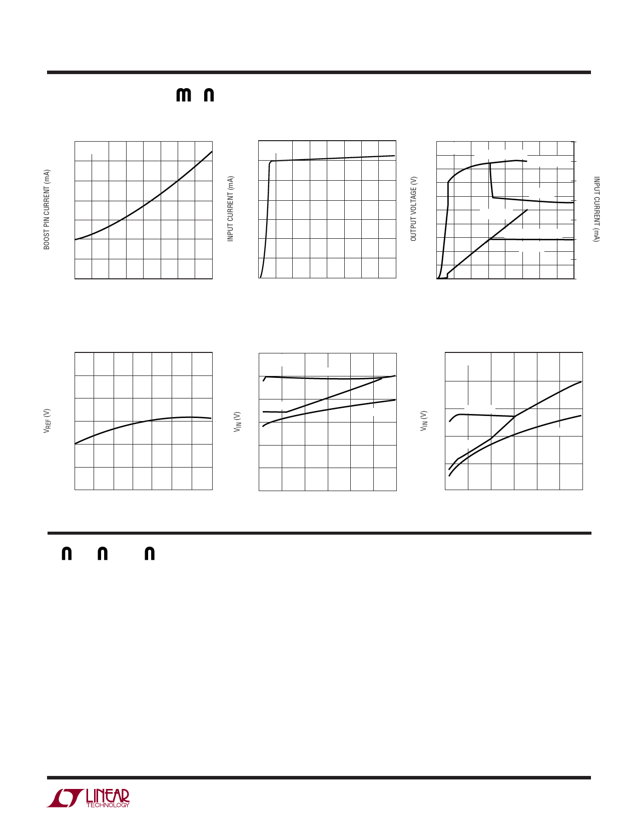
TYPICAL PERFOR A CE CHARACTERISTICS
Boost Pin Current
35
TA = 25°C
30
25
20
15
10
5
0
0
0.5
1.0
1.5
2.0
SWITCH CURRENT (A)
3475 G10
Reference Voltage
1.28
1.27
1.26
1.25
1.24
1.23
1.22
–50 –25
0 25 50 75
TEMPERATURE (˚C)
100 125
3475 G13
Quiescent Current
7
TA = 25°C
6
5
4
3
2
1
0
0
10
20
30
40
VIN (V)
3475 G11
Minimum Input Voltage, Single
1.5A White LED
6
TA = 25°C
5
TO START
4
TO RUN
3
LED VOLTAGE
2
1
0
0
0.5
1
1.5
LED CURRENT (A)
3475 G14
Open-Circuit Output Voltage and
Input Current
50 TA = 25°C
14
45
INPUT CURRENT
LT3475-1
12
40
35
10
30
LT3475
8
25
LT3475-1
20
6
15
OUTPUT VOLTAGE
4
10
LT3475
2
5
0
0
0
10
20
30
40
VIN (V)
3475 G12
Minimum Input Voltage, Two Series
Connected 1.5A White LEDs
10
TA = 25°C
9
8
TO START
7
TO RUN
6
LED VOLTAGE
5
0
0.5
1
1.5
LED CURRENT (A)
3475 G15
PI FU CTIO S
OUT1, OUT2 (Pins 1, 10): The OUT pin is the input to the
current sense resistor. Connect this pin to the inductor
and the output capacitor.
LED1, LED2 (Pins 2, 9): The LED pin is the output of
the current sense resistor. Connect the anode of the LED
here.
VIN (Pins 5, 6): The VIN pins supply current to the internal
circuitry and to the internal power switches and must be
locally bypassed.
SW1, SW2 (Pins 4, 7): The SW pin is the output of the
internal power switch. Connect this pin to the inductor,
switching diode and boost capacitor.
BOOST1, BOOST2 (Pins 3, 8): The BOOST pin is used to
provide a drive voltage, higher than the input voltage, to
the internal bipolar NPN power switch.
GND (Pins 15, Exposed Pad Pin 21): Ground. Tie the GND
pin and the exposed pad directly to the ground plane. The
exposed pad metal of the package provides both electrical
contact to ground and good thermal contact to the printed
circuit board. The exposed pad must be soldered to the
circuit board for proper operation. Use a large ground plane
and thermal vias to optimize thermal performance.
3475fb
5
Share Link: 