LT3486 データシートの表示(PDF) - Linear Technology
部品番号
コンポーネント説明
メーカー
LT3486 Datasheet PDF : 20 Pages
| |||
LT3486
APPLICATIONS INFORMATION
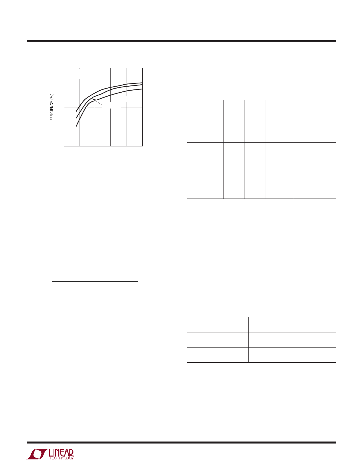
90
VIN = 5V
8/8 LEDs
80
RT = 63.4k
70
RT = 21.5k
60
RT = 39.1k
50
40
30
0
5
10
15
20
25
LED CURRENT (mA)
3486 F06b
Figure 6b. Efficiency Comparison for Different RT Resistors
Inductor Selection
The choice of the inductor will depend on the selection of
switching frequency of LT3486. The switching frequency
can be programmed from 200kHz to 2.5MHz. Higher
switching frequency allows the use of smaller inductors
albeit at the cost of increased switching losses.
The inductor current ripple (∆IL), neglecting the drop
across the Schottky diode and the switch, is given by:
( ) ∆IL
=
VIN(MIN) • VOUT(MAX) – VIN(MIN)
VOUT(MAX) • f • L
where:
L = Inductor
f = Operating frequency
VIN(MIN) = Minimum input voltage
VOUT(MAX) = Maximum output voltage
The ∆IL is typically set to 20% to 40% of the maximum
inductor current.
The inductor should have a saturation current rating greater
than the peak inductor current required for the application.
Also, ensure that the inductor has a low DCR (copper wire
resistance) to minimize I2R power losses. Recommended
inductor values range from 4.7µH to 22µH.
Several inductors that work well with the LT3486 are listed
in Table 1. Consult each manufacturer for more detailed
information and for their entire selection of related parts.
Table 1. Recommended Inductors
L
PART
(µH)
LQH55DN150M 15
LQH55DN220M 22
A915AY-4R7M 4.7
A915AY-6R8M 6.8
A915AY-100M
10
A918CY-100M
10
A918CY-150M
15
CDRH4D28-100 10
CDRH5D18-150 15
MAX
DCR
(Ω)
0.150
0.190
0.045
0.068
0.090
0.098
0.149
0.048
0.145
CURRENT
RATING
(A)
1.40
1.20
2.49
2.01
1.77
1.22
0.94
1.30
0.97
VENDOR
Murata
(814) 237-1431
www.murata.com
Toko
(847) 297-0070
www.toko.com
Sumida
(847) 956-0666
www.sumida.com
Capacitor Selection
The small size of ceramic capacitors make them ideal
for LT3486 applications. Use only X5R and X7R types
because they retain their capacitance over wider voltage
and temperature ranges than other types such as Y5V
or Z5U. A 4.7µF or larger input capacitor is sufficient for
most applications. Always use a capacitor with sufficient
voltage rating.
Table 2 shows a list of several ceramic capacitor manufac-
turers. Consult the manufacturers for detailed information
on their entire selection of ceramic parts.
Table 2. Ceramic Capacitor Manufacturers
Taiyo Yuden
AVX
Murata
(408) 573-4150
www.t-yuden.com
(803) 448-9411
www.avxcorp.com
(714) 852-2001
www.murata.com
Diode Selection
Schottky diodes with their low forward voltage drop and
fast reverse recovery, are the ideal choices for LT3486
applications. The diode conducts current only during the
switch off time. The peak reverse voltage that the diode
must withstand is equal to the regulator output voltage.
3486fe
11
Share Link: 