3724EFE データシートの表示(PDF) - Linear Technology
部品番号
コンポーネント説明
メーカー
3724EFE Datasheet PDF : 26 Pages
| |||
LT3724
OPERATIONS (Refer to Functional Diagram)
The LT3724 is a PWM controller with a constant frequency,
current mode control architecture. It is designed for low
to medium power, switching regulator applications. Its
high operating voltage capability allows it to step-up
or down input voltages up to 60V without the need for
a transformer. The LT3724 is used in nonsynchronous
applications, meaning that a freewheeling rectifier diode
(D1 of Function Diagram) is used instead of a bottom
side MOSFET. For circuit operation, please refer to the
Functional Diagram of the IC and Typical Application on
the front page of the data sheet. The LT3800 is a similar
part that uses synchronous rectification, replacing the
diode with a MOSFET in a step-down application.
Main Control Loop
During normal operation, the external N-channel MOSFET
switch is turned on at the beginning of each cycle. The
switch stays on until the current in the inductor exceeds
a current threshold set by the DC control voltage, VC, the
output of the voltage control loop. The voltage control loop
monitors the output voltage, via the VFB pin voltage, and
compares it to an internal 1.231V reference. It increases
the current threshold when the VFB voltage is below the
reference voltage and decreases the current threshold
when the VFB voltage is above the reference voltage. For
instance, when an increase in the load current occurs,
the output voltage drops causing the VFB voltage to drop
relative to the 1.231V reference. The voltage control loop
senses the drop and increases the current threshold. The
peak inductor current is increased until the average induc-
tor current equals the new load current and the output
voltage returns to regulation.
Current Limit/Short-Circuit
The inductor current is measured with a series sense
resistor (see the Typical Application on the front page).
When the voltage across the sense resistor reaches the
maximum current sense threshold, typically 150mV, the
TG MOSFET driver is disabled for the remainder of that
cycle. If the maximum current sense threshold is still ex-
ceeded at the beginning of the next cycle, the entire cycle
is skipped. Cycle skipping keeps the inductor currents to
a controlled value during a short-circuit, particularly when
VIN is high. Setting the sense resistor value is discussed
in the “Application Information” section.
VCC/Boosted Supply
An internal VCC regulator provides VIN derived gate-drive
power for start-up under all operating conditions with
MOSFET gate charge loads up to 90nC. The regulator can
operate continuously in applications with VIN voltages
up to 60V, provided the VIN voltage and/or MOSFET gate
charge currents do not create excessive power dissipa-
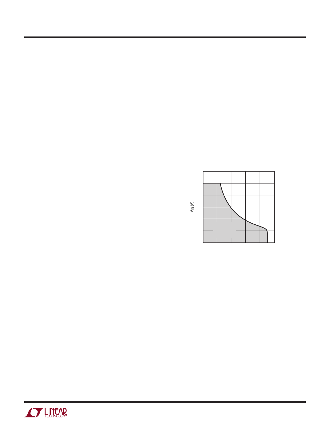
tion in the IC. Safe operating conditions for continuous
regulator use are shown in Figure 1. In applications where
these conditions are exceeded, VCC must be derived from
an external source after start-up. The LT3724 regulator
can, however, be used for “full time” use in applications
where short-duration VIN transients exceed allowable
continuous voltages.
70
60
50
40
30
SAFE
20
OPERATING
AREA
10
0
20
40
60
80
100
MOSFET TOTAL GATE CHARGE (nC)
3724 F01
Figure 1. VCC Regulator Continuous Operating Conditions
For higher converter efficiency and less power dissipa-
tion in the IC, VCC can also be supplied from an external
supply such as the converter output. When an external
supply back drives the internal VCC regulator through an
external diode and the VCC voltage is pulled to a diode
above its regulation voltage, the internal regulator is dis-
abled and goes into a low current mode. VCC is the bias
supply for most of the internal IC functions and is also
used to charge the bootstrapped capacitor (CBOOST) via an
external diode. The external MOSFET switch is biased from
the bootstrapped capacitor. While the external MOSFET
switch is off, an internal BJT switch, whose collector is
connected to the SW pin and emitter is connected to the
PGND pin, is turned on to pull the SW node to PGND and
recharge the bootstrap capacitor. The switch stays on until
3724fd
9
Share Link: 