LTC2901-2IGN データシートの表示(PDF) - Linear Technology
部品番号
コンポーネント説明
メーカー
LTC2901-2IGN
Linear Technology

LTC2901-2IGN Datasheet PDF : 16 Pages
| |||
LTC2901
ABSOLUTE AXI U RATI GS (Notes 1, 2, 3)
V1, V2, V3, V4, VPG ..................................... – 0.3V to 7V
RST (LTC2901-1/LTC2901-3) ..................... – 0.3V to 7V
RST (LTC2901-2/LTC2901-4) ....... – 0.3V to (V2 + 0.3V)
COMPX ....................................................... – 0.3V to 7V
CWT, WDI, WDO ......................................... – 0.3V to 7V
VREF, CRT, TOL ............................ – 0.3V to (VCC + 0.3V)
Reference Load Current (IVREF) ............................ ±1mA
V4 Input Current (–ADJ Mode) ............................. –1mA
Operating Temperature Range
LTC2901-1C/LTC2901-2C/
LTC2901-3C/LTC2901-4C ....................... 0°C to 70°C
LTC2901-1I/LTC2901-2I/
LTC2901-3I/LTC2901-4I .................... –40°C to 85°C
Storage Temperature Range .................. – 65°C to 150°C
Lead Temperature (Soldering, 10 sec)................... 300°C
UW U
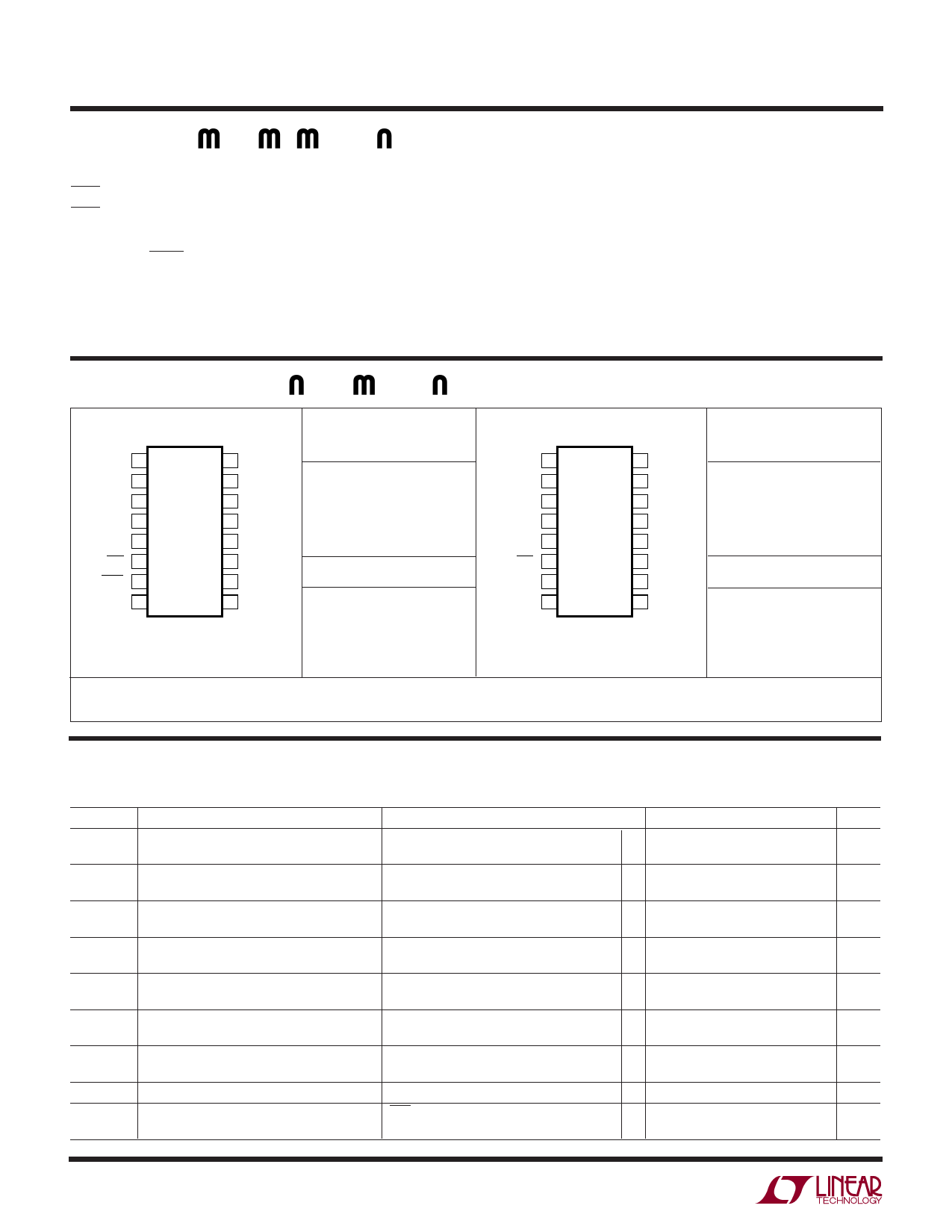
PACKAGE/ORDER I FOR ATIO
TOP VIEW
COMP3 1
COMP1 2
V3 3
V1 4
CRT 5
RST 6
WDO 7
WDI 8
16 COMP2
15 COMP4
14 V2
13 V4
12 VREF
11 VPG
10 GND
9 CWT
GN PACKAGE
16-LEAD PLASTIC SSOP
TJMAX = 125°C, θJA = 110°C/W
ORDER PART
NUMBER
LTC2901-1CGN
LTC2901-2CGN
LTC2901-1IGN
LTC2901-2IGN
GN16 PART MARKING
29011
29012
29011I
29012I
TOP VIEW
COMP3 1
COMP1 2
V3 3
V1 4
CRT 5
RST 6
TOL 7
WDI 8
16 COMP2
15 COMP4
14 V2
13 V4
12 VREF
11 VPG
10 GND
9 CWT
GN PACKAGE
16-LEAD PLASTIC SSOP
TJMAX = 125°C, θJA = 110°C/W
ORDER PART
NUMBER
LTC2901-3CGN
LTC2901-4CGN
LTC2901-3IGN
LTC2901-4IGN
GN16 PART MARKING
29013
29014
29013I
29014I
Order Options Tape and Reel: Add #TR Lead Free: Add #PBF Lead Free Tape and Reel: Add #TRPBF
Lead Free Part Marking: http://www.linear.com/leadfree/
Consult LTC Marketing for parts specified with wider operating temperature ranges.
ELECTRICAL CHARACTERISTICS The ● denotes the specifications which apply over the full operating
temperature range, otherwise specifications are at TA = 25°C. VCC = 5V, unless otherwise noted. (Notes 3, 4)
SYMBOL PARAMETER
CONDITIONS
MIN TYP MAX
VRT50
5V, 5% Reset Threshold
5V, 10% Reset Threshold
V1 Input Threshold
● 4.600 4.675 4.750
● 4.350 4.425 4.500
VRT33
3.3V, 5% Reset Threshold
3.3V, 10% Reset Threshold
V1, V2 Input Threshold
● 3.036 3.086 3.135
● 2.871 2.921 2.970
VRT30
3V, 5% Reset Threshold
3V, 10% Reset Threshold
V2 Input Threshold
● 2.760 2.805 2.850
● 2.610 2.655 2.700
VRT25
2.5V, 5% Reset Threshold
2.5V, 10% Reset Threshold
V2, V3 Input Threshold
● 2.300 2.338 2.375
● 2.175 2.213 2.250
VRT18
1.8V, 5% Reset Threshold
1.8V, 10% Reset Threshold
V3, V4 Input Threshold
● 1.656 1.683 1.710
● 1.566 1.593 1.620
VRT15
1.5V, 5% Reset Threshold
1.5V, 10% Reset Threshold
V3, V4 Input Threshold
● 1.380 1.403 1.425
● 1.305 1.328 1.350
VRTA
ADJ, 5% Reset Threshold
ADJ, 10% Reset Threshold
V3, V4 Input Threshold
● 0.492 0.500 0.508
● 0.466 0.473 0.481
VRTAN
VCC
– ADJ Reset Threshold
Minimum Internal Operating Voltage
V4 Input Threshold
RST, COMPX in Correct Logic State;
VCC Rising Prior to Program
●
– 18
0
18
●
1
UNITS
V
V
V
V
V
V
V
V
V
V
V
V
V
V
mV
V
2901fb
2
Downloaded from: http://www.datasheetcatalog.com/
Share Link: