LTC2903 データシートの表示(PDF) - Linear Technology
部品番号
コンポーネント説明
メーカー
LTC2903 Datasheet PDF : 16 Pages
| |||
LTC2903-1
APPLICATIO S I FOR ATIO
Power-Up
The LTC2903-1 issues a logic low on the RST output when
an input supply voltage resides below the prescribed
threshold voltage. Ideally, the RST logic output would
remain low with the input supply voltage down to zero
volts. Most supervisors lack pull-down capability below
1V. The LTC2903-1 power supply supervisors incorporate
a new low voltage pull-down circuit that can hold the RST
line low with as little as 200mV of input supply voltage on
V1, V2 or V3. The pull-down circuit helps maintain a low
impedance path to ground, reducing the risk of floating the
RST node to undetermined voltages. Such voltages may
trigger external logic causing erroneous reset operation(s).
Furthermore, a mid-scale voltage could cause external
circuits to operate in the middle of their voltage transfer
characteristic, consuming more quiescent current than
normal. These conditions could cause serious system
reliability problems.
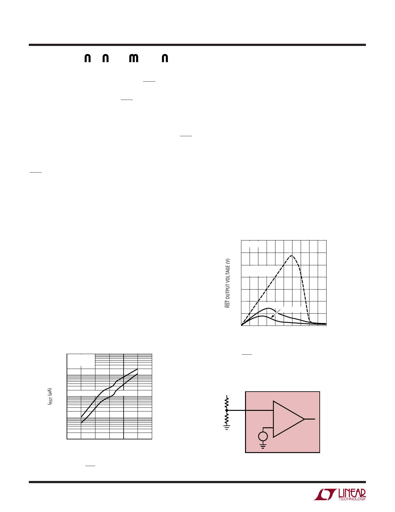
When V1, V2 and V3 are ramped simultaneously, the reset
pull-down current increases up to three times the current
that may be pulled with a single input. Figure 1 demon-
strates the reset pin current sinking ability for single
supply and triple supply-tracking applications. Figure 2
shows a detailed view of the reset pin voltage with a 10k
pull-up resistor to V1.
The LTC2903-1 supervisors derive their internal supply
voltage (VCC) automatically from the greater voltage on the
V1 and V2 inputs. With all supply inputs above threshold,
the quiescent current drawn from VCC is 20µA (typ).
10000
TA = 25°C
VRST = 0.3VCC
1000
Supply Monitoring
The LTC2903-1 accurately monitors four inputs in a small
6-lead SOT-23 package. The low voltage reset output
includes an integrated 200ms reset delay timer. The reset
line pulls high 200ms after all voltage inputs exceed their
respective thresholds. The reset output remains low dur-
ing power-up, power-down and brownout conditions on
any of the voltage inputs.
For applications requiring an adjustable trip threshold, use
the V4 input on the LTC2903-A1. Connect the tap point on
an external resistive divider (R1, R2) placed between the
positive voltage being sensed and ground, to the high
impedance input on V4. The LTC2903-A1 compares the
voltage on the V4 pin to the internal 0.5V reference.
Figure␣ 3 shows a generic setup for the positive adjustable
application.
0.7 TA = 25°C
0.6
0.5
COMPETITION
PART
0.4
0.3
0.2
V1 ONLY
V1 = V2 = V3
0.1
0
0 0.1 0.2 0.3 0.4 0.5 0.6 0.7 0.8 0.9 1.0
V1 (V)
39031 F02
Figure 2. RST Output Voltage with a 10k Pull-Up to V1
(Enlarged Area of Detail)
100 V1 = V2 = V3
V1 ONLY
10
1
0 0.2 0.4 0.6 0.8 1.0 1.2
VCC (V)
29031 F01
Figure 1. RST Pull-Down Current vs VCC
10
VTRIP
R1
1%
V4
R2
1%
LTC2903-A1
–
+
0.5V +–
29031 F03
Figure 3. Setting the Positive Adjustable Trip Point
29031f
Share Link: 