LTC6801HG-TRPBF(RevC) データシートの表示(PDF) - Linear Technology
部品番号
コンポーネント説明
メーカー
LTC6801HG-TRPBF Datasheet PDF : 28 Pages
| |||
LTC6801
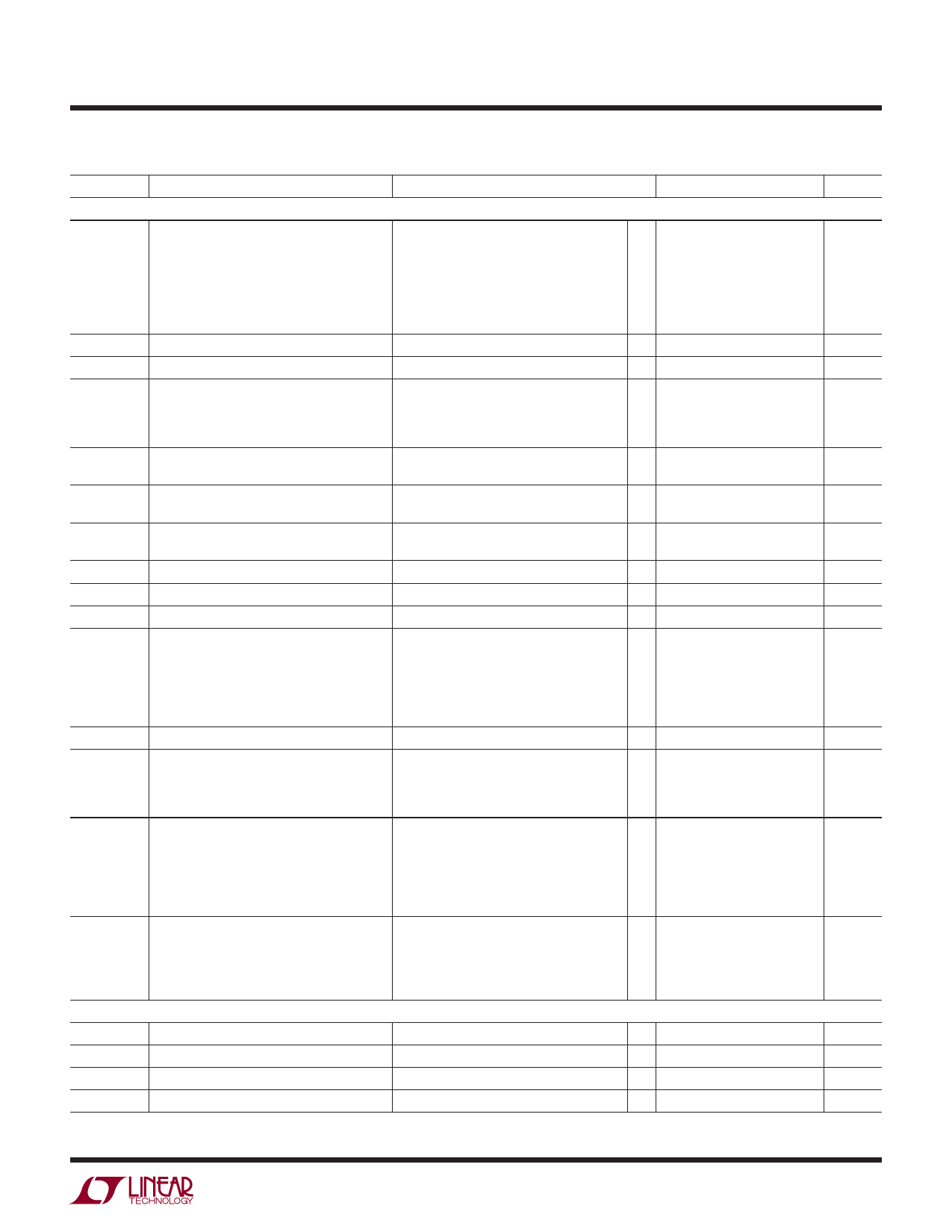
ELECTRICAL CHARACTERISTICS The l denotes the specifications which apply over the full operating
temperature range, otherwise specifications are at TA = 25°C, V+ = 43.2V, V– = 0V unless otherwise noted.
SYMBOL
PARAMETER
CONDITIONS
MIN TYP MAX
UNITS
DC Specifications
VERR
Overvoltage (OV) or Undervoltage (UV)
(Note 2)
Detection Level Error
2.106V ≤ VCELL ≤ 4.498V
2.106V ≤ VCELL ≤ 4.498V
1.531V ≤ VCELL < 2.106V
1.531V ≤ VCELL < 2.106V
VCELL = 0.766V
VCELL = 0.766V
VS
Supply Voltage, V+ Relative to V–
VERR Specifications Met
–0.8
l –1
–1
l –1.3
–1.5
l –2
l 10
0.8
%
1
%
1
%
1.3
%
1.5
%
2
%
50
V
VCELL
VCM
Cell Voltage Range
Common Mode Voltage Range Measured
Relative to V–
Full Scale Voltage Range
VERR Specifications Met
Range of Inputs Cn, n = 3 to 11
Range of Input C2
Range of Input C1
5
V
l 1.8
l 1.2
l
0
5•n
V
10
V
5
V
VTV
Temperature Input Detection Level Error 10V < V+ < 50V
(Relative to VREF/2)
HYS
UV/OV Detection Hysteresis Error
10V < V+ < 50V
(Relative to Selected Value)
l –13
l –25
17
mV
25
%
VREF
Reference Pin Voltage
VREF Pin Loaded With 100k to V–
3.043 3.058 3.073
V
l 3.038 3.058 3.078
V
Reference Voltage Temperature Coefficient
8
ppm/˚C
Reference Voltage Hysteresis
50
ppm
Reference Voltage Long Term Drift
60
ppm/√khr
VREG
Regulator Pin Voltage
10V < VS < 50V, No Load
LTC6801IG
LTC6801HG
10V < VS < 50V, ILOAD = 4mA
LTC6801IG
LTC6801HG
l 4.5
5
5.5
V
l 4.5
5
5.7
V
l 4.1
4.8
V
l 4.1
4.8
V
Regulator Pin Short Circuit Current Limit
l
5
9
mA
IB
Input Bias Current
In/Out of Pins C1 Thru C12
When Measuring Cells During Self Test
100
µA
When Measuring Cells
l –10
10
µA
When Idle
1
nA
IM
Supply Current, Monitor Mode
Current Into the V+ Pin While Monitoring
for UV and OV Conditions, FENA = 10kHz
Continuous Monitoring
600
750 1000
µA
Continuous Monitoring
l 500
750 1100
µA
Monitor Every 130ms (Note 3)
l 110
200
320
µA
Monitor Every 500ms (Note 3)
l 50
100
160
µA
IQS
Supply Current, Idle
Current into the V+ Pin When Idle, FENA = 0
LTC6801IG
23
30
42
µA
l 20
30
45
µA
LTC6801HG
23
30
42
µA
l 20
30
48
µA
LTC6801 Timing Specifications
TCYCLE
FENA
Measurement Cycle Time
Valid EIN/EIN Frequency
DC = CC1 = CC0 = VREG
l 13
15.5
19
ms
l
2
40
kHz
TENA
Valid EIN/EIN Period = 1/ FENA
l 25
500
µs
DCENA
Valid EIN/EIN Duty Cycle
FENA = 40kHz
l 40
60
%
For more information www.linear.com/LTC6801
6801fc
3
Share Link: 