LX2203A データシートの表示(PDF) - Microsemi Corporation
部品番号
コンポーネント説明
メーカー
LX2203A Datasheet PDF : 11 Pages
| |||
LX2203A
TM
®
Li-Ion Battery Charger
PRODUCTION DATA SHEET
APPLICATION NOTE
GENERAL DESCRIPTION
The LX2203A is designed to charge a single cell Lithium
Ion (Li-ion) battery using two modes: a constant current
mode, where the charge current is held constant and the
battery terminal voltage rises to 4.2V; this is followed by
constant voltage mode, where the battery voltage is held at
4.2V and the charge current starts to taper off. Once the taper
current reaches the charge termination current level the
charge cycle is ended and the STAT indicator turns off. If
the fully charged battery terminal voltage drops to 4.07V, the
battery charge cycle will be restarted.
PROTECTION FEATURES
Conditioning Current Mode – If the battery terminal
voltage is less than 2.65V, the battery charger will reduce the
charge current to 5%. This also protects the appliance from
overheating by trying to drive the full charging current into a
damaged battery.
Under Voltage Lockout – The charge cycle will not start
until the VIN voltage rises above 4.2V. Hysteresis prevents
chattering on and off.
Thermal Control loop – If the power dissipation of the
charger becomes excessive, the charge current will be
reduced to prevent the die temperature from getting above
150°C. This does not cause the charge cycle to stop.
Reverse current blocking – If VIN is grounded, current
will not flow from the battery through the charger. No
external blocking diode is required on the input.
Sleep Mode – If the EN pin is logic low or if VIN is
removed, the charger enters a sleep mode where a very low
quiescent current prevents drain from the battery.
LAYOUT GUIDELINES
• It is important when laying out the LX2203A to place
10µF ceramic capacitors close to the VIN and VBAT IC
terminals to filter switching transients.
• It is important to provide a low thermal impedance
path from the thermal pad on the bottom of the LX2203A
package to the ground plane of the circuit board to maximize
the heat dissipation. To minimize charge time it is best not to
rely on the thermal control feature as this feature will extend
the charging time when activated.
TERMINATION CURRENT PROGRAMMING
The charge termination current (or minimum taper
current) is set by selecting a value for the CTP resistor using
the following formula:
7500
R CTP =
I TERM
For example, for a termination current of 50mA set RCTP
= 150k. This formula applies to termination currents
ranging from 20mA to 500mA.
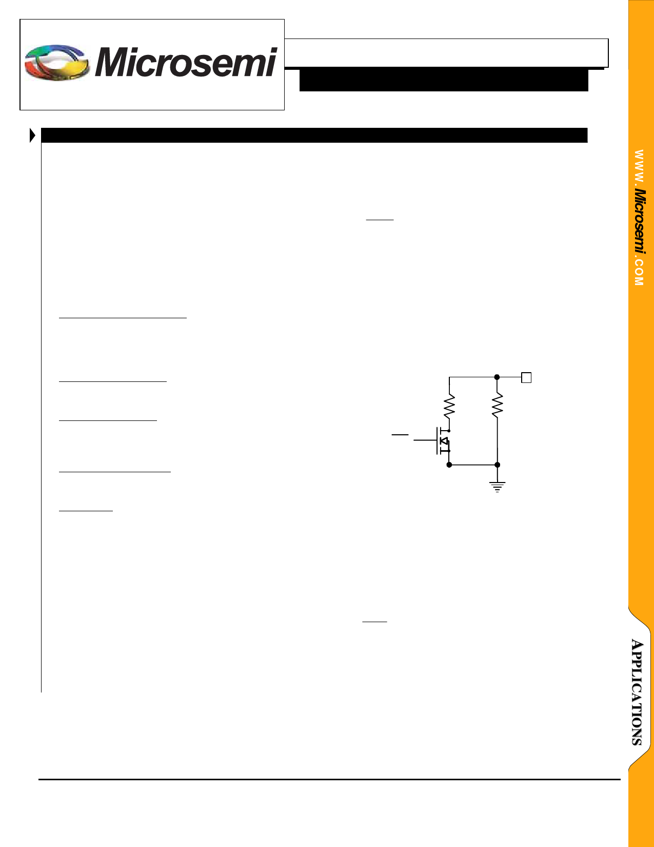
It is possible to change the termination current to different
levels for different charge rates. For a “quick charge”, the
termination current can be set to about 50% of the constant
current level; this charges the battery to about 75% capacity.
For a full charge (taking several hours) the termination
current can be set to 5% of the constant current level. The
circuit below allows switching between the two levels:
CTP
16.5k
150k
Quick/Slow
Figure 5 – 500mA or 50mA termination current
CONSTANT CHARGE CURRENT PROGRAMMING
The charge current during the constant current charge
mode is programmable by controlling the current flowing
from the CCP pin. A graph showing this relationship is
included in this specification. The CCP pin is regulated to
1.25V when the charger is active. Connecting a resistor from
the CTP to ground will produce a CTP current of:
1.25
ICTP =
R CCP
(Continued on next page)
Copyright © 2004
Rev. 1.0a, 2005-10-21
Microsemi
Integrated Products Division
11861 Western Avenue, Garden Grove, CA. 92841, 714-898-8121, Fax: 714-893-2570
Page 8
Share Link: 