LX2205 データシートの表示(PDF) - Microsemi Corporation
部品番号
コンポーネント説明
メーカー
LX2205 Datasheet PDF : 14 Pages
| |||
LX2205
® 1A Li-Ion Battery Charger with Power Source Management
TM
PRODUCTION DATA SHEET
THEORY OF OPERATION
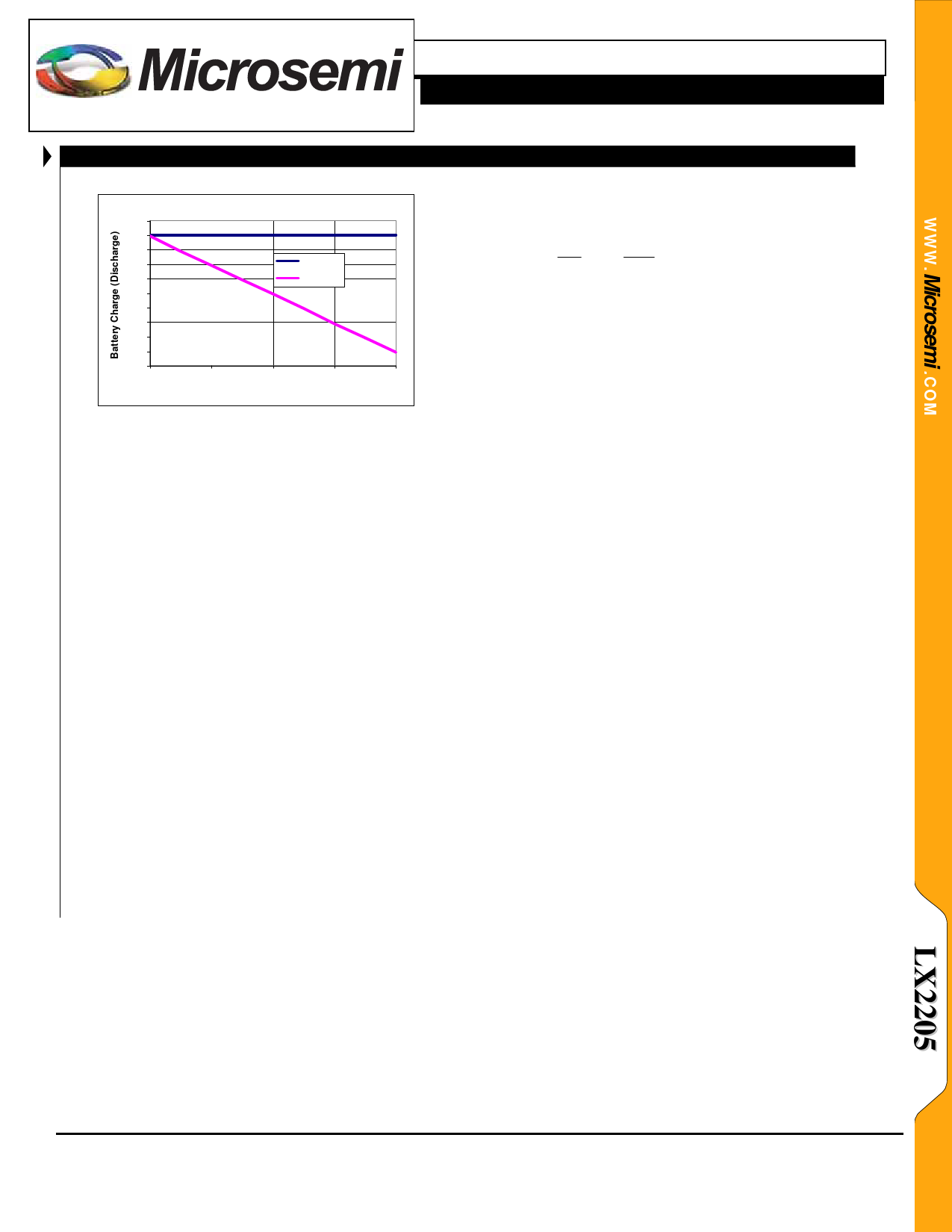
Battery Current w ith 100m A USB Current Lim it
120
100
80
60
USB Limit
40
Battery
20
0
-20
-40
-60
-80
0
40
80
120
160
System Load Current (m A)
REDUCED USB CHARGE TIME
The isolated battery topology reduces charge time from
the USB port when the appliance is turned on while also
charging. Because the system power rail can be a higher
voltage than the battery voltage, the system will require less
power from the USB source which leaves more power
available to charge the battery quickly. For example, if the
system draws 1W, and the USB input is 5V, the system
draws 1W/5V = 200mA from the USB source; this leaves
300mA to charge the battery. In a topology where the load
connects directly to the battery (as is done with
conventional non-isolated linear chargers), if the average
battery voltage is 3.7V, the system will draw 1W/3.7V =
270mA from the USB source, this leaves only 230mA to
charge the battery. In this case the LX2205 will charge the
battery 30% faster.
USB SUSPEND
When the SUSP pin is pulled high, less than 25μA is
pulled from the USB port. The rest of the LX2205,
however, continues to function normally. If an adapter is
applied, the effect of SUSP is negligible. If the system is
running off both USB and the battery and SUSP is logic
high, the system load will be transferred 100% to the
battery.
SHDN
When SHDN is logic high, the LX2205 is placed in a
total shutdown mode; no current will flow between SYS,
USB and BAT. Quiescent current is 25μA during
shutdown. CHG and DONE are high impedance (off) in
SHDN mode.
UCL
The UCL pin is used to select the current limit level for
the USB input. When the UCL pin is a logic high the
maximum current level as determined by the CUS resistor
is selected; when the UCL pin is a logic low, the current
limit is set to 20% of the maximum level.
POWER OR-ING (SYS TO BAT AND BAT TO SYS)
When the power is removed from both MDC and
USB, the battery current flows from BAT to SYS and thus
provides power to the load without the need for any
external switches or monitoring circuits. There is a circuit
equivalent of an ideal diode (patent-pending bi-directional
MOSFET) in the LX2205 between the BAT pin and SYS
pin. This ideal diode appears as a low impedance to high
forward current and presents a high impedance to low
discharge currents or potentially reverse charge currents.
For small forward currents, the ideal diode regulates a
small forward voltage. This small voltage allows the
power sense circuitry to determine whether an input power
source is present even if the current through the ideal diode
is less than 1mA. This feature makes it virtually
impossible to charge the battery (unregulated) in reverse
through the ideal diode and also enables the battery to
assist a current limited input power source without
chattering even if only a few mA of battery current are
required.
Copyright © 2007
Rev. 1.0a, 2007-03-02
Microsemi
Analog Mixed Signal Group
11861 Western Avenue, Garden Grove, CA. 92841, 714-898-8121, Fax: 714-893-2570
Page 10
Share Link: 