LX2205 データシートの表示(PDF) - Microsemi Corporation
部品番号
コンポーネント説明
メーカー
LX2205 Datasheet PDF : 14 Pages
| |||
LX2205
® 1A Li-Ion Battery Charger with Power Source Management
TM
PRODUCTION DATA SHEET
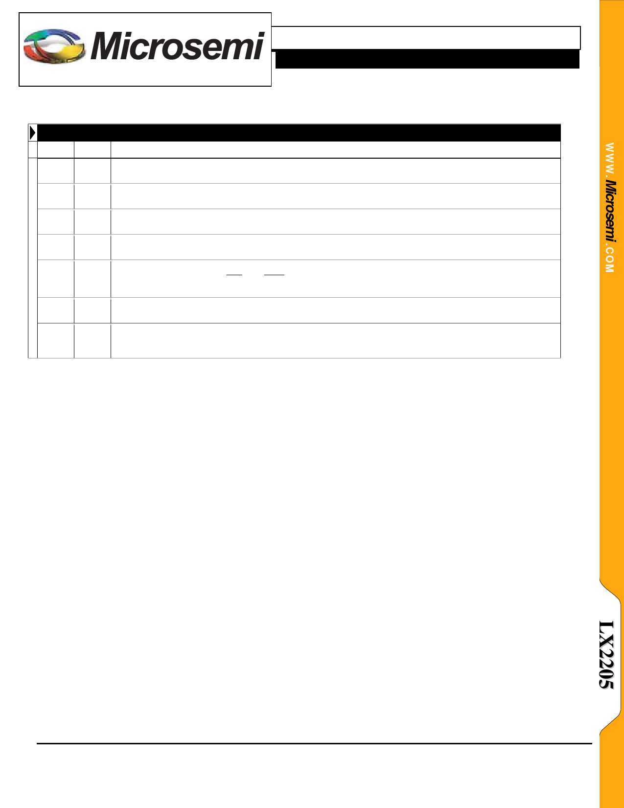
Name Pin
MDC 5
SHDN 6
SUSP 7
SYS
3
TFB 16
USB
4
UCL
8
FUNCTIONAL PIN DESCRIPTION (CONTINUED)
Description
Main DC Input – This input is a voltage monitoring input (and not a high current input). Its purpose is to
determine the presence of the main DC input to provide lockout for the USB power input.
Shutdown – Pulling this pin high will disable the entire device including the battery discharge path and place
the device in a low power sleep mode. This pin has an internal pull-down.
Suspend (USB) – Pulling this pin high will prevent current from being drawn from the USB input pin. The rest
of the chip functions are unaffected. This pin has an internal pull-down.
System Power Node – This pin provides power to user system. SYS voltage provided will range from the
battery voltage to the wall adapter and/or USB voltage.
Temperature Feedback – Charging is suspended when the TFB pin falls below 29% (typ) of VSYS or rises
above 74% (typ) of VSYS. CHG and DONE pins remain in their prior state during a TFB event. Connecting the
TFB pin to GND disables the TFB function.
USB Power Input – USB compliant input.
USB Current Limit – A high logic level will select the high USB current level determined by the programming of
the CUS pin. A low logic level will select a level that is 20% of the high USB current level. This pin has an
internal pull-down.
Copyright © 2007
Rev. 1.0a, 2007-03-02
Microsemi
Analog Mixed Signal Group
11861 Western Avenue, Garden Grove, CA. 92841, 714-898-8121, Fax: 714-893-2570
Page 3
Share Link: 