LX2205 データシートの表示(PDF) - Microsemi Corporation
部品番号
コンポーネント説明
メーカー
LX2205 Datasheet PDF : 14 Pages
| |||
LX2205
® 1A Li-Ion Battery Charger with Power Source Management
TM
PRODUCTION DATA SHEET
THEORY OF OPERATION
BATTERY CHARGER GENERAL DESCRIPTION
The LX2205 is designed to charge a single cell Lithium
Ion or Lithium Polymer battery using two steps: a constant
current step followed by a constant voltage step. The basic
charger function uses the SYS pin as an input and BAT pin
as the output. The LX2205 charger has a programmable
maximum current (programmable by the resistor value
between the CCP pin and GND) which is the maximum
charging current during the Constant Current Mode of the
charging profile. The charger will terminate constant
voltage charging once the current drops below the taper
current setting (programmable by the resistor value between
CTP pin and GND).
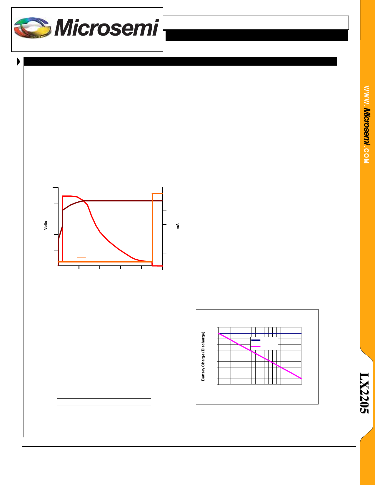
Two step charger profile:
5
Battery Voltage
1000
4
800
3
600
Battery Current
2
400
1
200
CHG Voltage
0
Time
CONDITIONING CURRENT CHARGE MODE
A conditioning current is applied to a battery that is
deeply discharged and has a terminal voltage less than 60%
of the constant voltage level. The conditioning current is
5% of the CCP programmable constant current level. Once
the battery terminal voltage exceeds the 60% level, the full
constant current level is applied (unless charging current is
limited by one of the other charger control loops).
CHARGE TERMINATION MODE
To increase system battery life and avoid float charging,
the LX2205 disconnects the charger once the battery has
been fully charged. The charge termination state occurs at
the end of constant voltage mode. The charge status
indicators change state when charging is completed.
STATES
Charge in process
Charge completed
Input power removed
CHG
ON
OFF
OFF
DONE
OFF
ON
OFF
Using the taper current to terminate the charge cycle is
particularly advantageous in an isolated battery topology
such as the LX2205, because when an external power
source is applied to the appliance with the appliance turned
on, the power to the appliance and the power to the battery
take separate paths. This separate path allows the battery
charge current to be monitored accurately. Compared with
charger controllers that rely on a fixed timeout period
terminating by taper current allow for the shortest possible
battery charge time.
TOP OFF CHARGE MODE
Once the charger has completed a charge cycle, if power
remains applied, the LX2205 enters a voltage monitoring
mode. In this mode the LX2205 monitors the battery
terminal voltage and applies a top off charge if the battery
voltage drops by more than 3% of VCVL. This feature is
especially important for charging systems in equipment
where usage is infrequent.
USB CHARGE MODE AND CURRENT LIMIT
The LX2205 is fully compliant with, and supports, the
USB specifications – the Low Power Peripheral (100mA)
and High Power Peripheral (500mA). The UCL logic input
selects the USB charge current level. The LX2205 senses
the current flowing from the USB terminal to the SYS
terminal. The LX2205 will first try to reduce the
combined USB load by scaling back the battery charging
current. Once the charger has scaled back the charge
current to zero, if the load demands more current than the
USB bus can supply the VSYS voltage will drop down to the
battery voltage level and the battery will supply the
additional current demand. This is illustrated in the
following two charts.
Battery Current w ith 500m A USB Current Lim it
600
500
400
300
200
100
0
-100
-200
-300
-400
0
USB Limit
Battery
200
400
600
800
System Load Current (m A)
Copyright © 2007
Rev. 1.0a, 2007-03-02
Microsemi
Analog Mixed Signal Group
11861 Western Avenue, Garden Grove, CA. 92841, 714-898-8121, Fax: 714-893-2570
Page 9
Share Link: 