LX2207ILD データシートの表示(PDF) - Microsemi Corporation
部品番号
コンポーネント説明
メーカー
LX2207ILD Datasheet PDF : 14 Pages
| |||
LX2207
Three Level Lithium Ion Battery Charger
®
TM
PRODUCTION DATA SHEET
APPLICATION NOTE
LAYOUT
In the layout of the Printed Circuit Board (PCB) it is
important to provide a solid path from the IC power and
ground pins to the power and ground planes of the PCB to
provide a good conduction path for heat. This insures the
LX2207 stays cool and can provide the maximum charge
current to minimize the time required to charge the battery.
For stability, and to reduce turn on – turn off transients, it
is important to place capacitors close to the IN and BAT
pins. Use a 10uF capacitor (X5R or X7R dielectric) for this
purpose.
The CMP pin resistor and capacitor should be located
close to the CMP pin. The CMP pin is located next to the
IN pin to facilitate this. The 1K resistor is not required for
stability, but reduces the inrush current into the CMP pin
when the IN voltage transient is applied.
CURRENT PROGRAMMING RESISTORS
The LX2207 has two programming resistors to control
the battery charging current during the constant current
charging mode of the battery charging cycle. When the
H/L pin is high (selecting the High Current charging mode),
the charge current is determined by the value of the HCP
programming resistor. The maximum charge current is
determined by the programming current at either the HCP
or LCP programming pins (depending on the state of H/L);
the range of each of these channels is identical. The
programming current is the HCP or LCP pin voltage
(typically 1.25V) divided by the value of the programming
resistor. For example, the HCP current with a 110k resistor
to GND is:
Using the table below it can be seen that for a
programming current value of 11.4µA, the corresponding
maximum charge current is 92mA.
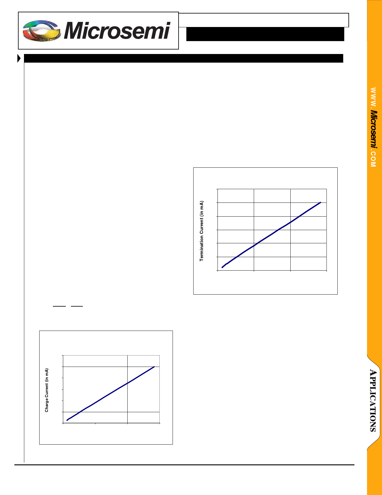
The termination current determines the point at which
the charge cycle is terminated and the battery is determined
to be fully charged. The termination current is determined
by the value of the HCP programming current as
determined by the HCP programming resistor. For a value
of IHCP = 11.4µA (as was used in the previous example),
the termination current from the chart below can be seen to
be 9mA.
Term ination Current vs IHCP
120
100
80
60
40
20
0
0.00
50.00
100.00
IHCP (in uA)
150.00
IHCP
=
1.25
RHCP
= 1.25
110k
= 11.4µA
The termination current is always roughly 10% of the
maximum charge current set by the HCP resistor.
Charge Current vs IHCP (or ILCP)
1200
1000
800
600
400
200
0
0.00
50.00
100.00
IHCP (in uA)
150.00
INDEPENDENT TERMINATION CURRENT PROGRAMMING
For applications where a termination current other than
10% is required, the termination current can be set using
the HCP resistor and the charge current can be set using
the LCP resistor. In this case, the H/L pin is held low so
that the HCP charge mode is never utilized. In this way
the HCP pin only programs the termination current and
conditioning current.
Copyright © 2007
Rev. 1.0a, 2007-10-08
Microsemi
Analog Mixed Signal Group
11861 Western Avenue, Garden Grove, CA. 92841, 714-898-8121, Fax: 714-893-2570
Page 8
Share Link: 