LX2208 データシートの表示(PDF) - Microsemi Corporation
部品番号
コンポーネント説明
メーカー
LX2208 Datasheet PDF : 11 Pages
| |||
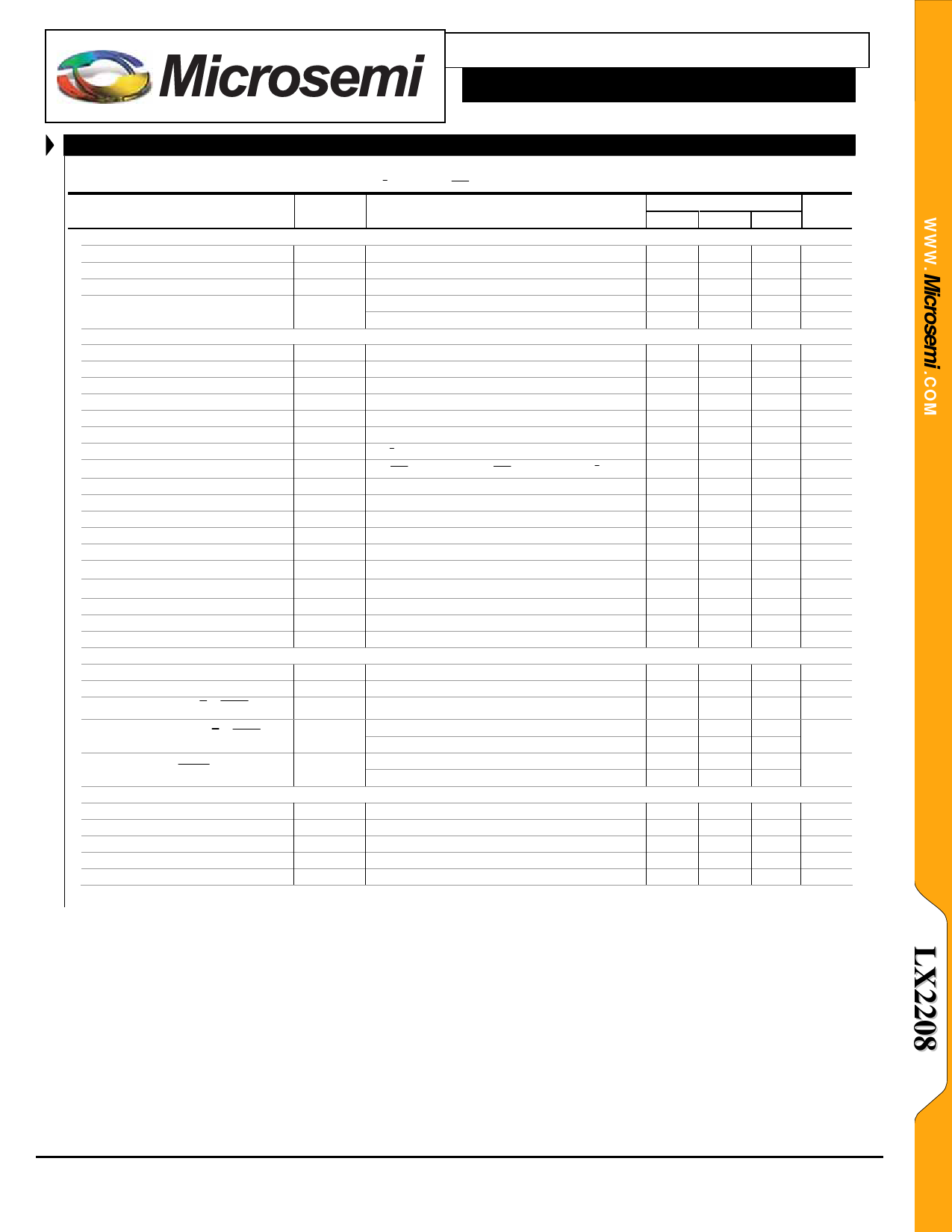
LX2208
2 Amp Three Level Lithium Ion Battery Charger
®
TM
PRODUCTION DATA SHEET
ELECTRICAL CHARACTERISTICS
Unless otherwise specified, the following specifications apply over the operating ambient temperature -40°C ≤ TA ≤ 85°C and the
following test conditions: VIN = 5.0V; VSD = Low; VH/ L = High, V 20% = High; VBAT = 3.6V; RHCP =15.8k, RLCP=15.8k; VTMP = 0V.
Parameter
` INPUT CIRCUITRY
Symbol
Test Conditions
LX2208
Units
Min Typ Max
Input Voltage
Under Voltage Charging Lockout
IN UVLO Hysteresis
VIN
VIN(UVLO)
Rising input VBAT = 2.8V
4.35
5
6
V
2.9
3.1
3.3
V
225
mV
IN Input Supply Current
` BATTERY CHARGER
IIN
VBAT = 4.2V (battery charged)
SD = High (shutdown mode)
1
2
mA
10
50
µA
Constant Voltage Charging
Constant Voltage Charging
Constant Voltage Charging
Charge Current
Charge Current
Charge Current
Low Level Charge Current
20% Charge Current Ratio
Condition Current
Condition Current
Conditioning Current Threshold
Termination Current
Termination Current
Top Off Threshold
Top Off Threshold
Battery Drain Current
Battery Drain Current
Battery Drain Current
` LOGIC
VBAT
VBAT
VBAT
IBAT
IBAT
IBAT
IBAT
IBAT
IBAT
IBAT
VBAT
IBAT
IBAT
VBAT
VBAT
IBAT
IBAT
IBAT
IBAT < 100mA @ 25°C (4.5V to 5.5V)
4.18
4.2
4.22
V
IBAT < 100mA (4.5V to 5.5V)
4.16
4.2
4.24
V
IBAT < 100mA (4.35V to 6V)
4.10
4.2
4.24
V
RHCP = 3.57k
RHCP = 7.15k
RHCP = 15.8k
1800 2000 2200 mA
900 1000 1100 mA
400 453 500 mA
VH/ L = Low
408 453 476 mA
I(V 20% = Low) / I (V 20% = High); VH/ L = Low 18
20
22
%
VBAT < VCCT; RHCP = 3.57k
VBAT < VCCT; RHCP = 7.15k
50
100 150 mA
25
50
75
mA
Rising Battery Voltage
2.5
2.7
2.9
V
RHCP = 3.57k
250
mA
RHCP = 7.15k
0°C ≤ TA ≤ 85°C
-40°C ≤ TA ≤ 85°C
VBAT = 4.2V (battery charged, VIN > 4.5V)
VBAT > VIN
125
mA
96
97
98
%
96
97
98.5
%
5
15
µA
5
15
µA
VSD=High (shutdown mode)
2.5
5
µA
STAT High Output
STAT Low Output
VSTAT
VSTAT
VIN = 5.0V, IDRV = -5mA
VIN = 5.0V, IDRV = 5mA
4.2
4.5
5
V
0.5
V
Input Logic : SD, H/ L , 20%
VLOG
Input Logic Threshold
450 725 1000 mV
Input Current : SD, H/ L , 20%
ILOG
Output Logic : DC OK
VLOG(OUT)
` BATTERY TEMPERATURE MONITOR
Input Current, VLOG = 2V
Input Current, VLOG = 0V
Logic Hi Output, 10k Pull up to 3.3V
Logic Low Output, ILOG = 10mA
0
2.5
5
µA
-2
0
2
3.2
V
0.5
Cold Threshold
Cold Threshold
Hot Threshold
Hot Threshold
TFB Disable Volt
VTFB
VTFB
VTFB
VTFB
VTFB
Rising Voltage
Falling Voltage
Falling Voltage
Rising Voltage
72
75
76.5 %VIN
70.5
72
74
% VIN
27
28
30
% VIN
28
30
31
% VIN
70
100 150 mV
Copyright © 2007
Rev. 1.0, 2007-04-03
Microsemi
Analog Mixed Signal Group
11861 Western Avenue, Garden Grove, CA. 92841, 714-898-8121, Fax: 714-893-2570
Page 3
Share Link: 