M29F002 データシートの表示(PDF) - STMicroelectronics
部品番号
コンポーネント説明
メーカー
M29F002 Datasheet PDF : 29 Pages
| |||
M29F002T, M29F002NT, M29F002B
Write. Write operations are used to give Instruction
Commands to the memory or to latch input data to
be programmed. A write operationis initiated when
Chip Enable E is Low and Write Enable W is Low
with Output Enable G High. Addresses are latched
on the falling edge of W or E whicheveroccurs last.
Commandsand InputData are latchedon the rising
edge of W or E whichever occurs first.
Output Disable. The data outputs are high imped-
ance when the Output Enable G is High with Write
Enable W High.
Standby. The memory is in standby when Chip
Enable E is High and the P/E.C. is idle. The power
consumption is reduced to the standby level and
the outputs are high impedance, independent of
the Output Enable G or Write Enable W inputs.
Automatic Standby. After 150ns of bus inactivity
and when CMOS levels are driving the addresses,
the chip automatically enters a pseudo-standby
mode where consumption is reduced to the CMOS
standby value, while outputs still drive the bus.
Electronic Signature. Two codes identifying the
manufacturerand the device can be read from the
memory. These codes allow programming equip-
ment or applications to automatically match their
interface to the characteristics of the M29F002.
The Electronic Signature is output by a Read op-
eration when the voltage applied to A9 is at VID and
address input A1 is Low. The manufacturer code is
output when the Address input A0 is Low and the
device code when this input is High. Other Address
inputs are ignored.
The Electronic Signature can also be read, without
raising A9 to VID, by giving the memory the Instruc-
tion AS.
Block Protection. Each block can be separately
protected against Program or Erase on program-
ming equipment. Block protection provides addi-
tional data security, as it disables all program or
erase operations. This mode is activated when
both A9 and G are raised to VID and an address in
the block is applied on A13-A17. The Block Protec-
tion algorithm is shown in Figure 14. Block protec-
tion is initiated on the edge of W falling to VIL. Then
after a delay of 100µs, the edge of W rising to VIH
ends the protection operations. Block protection
verify is achieved by bringing G, E, A0 and A6 to
VIL and A1 to VIH, while W is at VIH and A9 at VID.
Underthese conditions, reading the dataoutput will
yield 01h if the block defined by the inputs on
A13-A17 is protected. Any attempt to program or
erase a protected block will be ignored by the
device.
Block Temporary Unprotection. This feature is
available on M29F002T and M29F002B only. Any
previously protected block can be temporarily un-
protected in order to change stored data. The
temporaryunprotectionmode is activated by bring-
ing RPNC to VID. During the temporary unprotec-
tion mode the previously protected blocks are
unprotected.A block can be selected and data can
be modified by executing the Erase or Program
instruction with the RPNC signal held at VID. When
RPNC is returned to VIH, all the previously pro-
tected blocks are again protected.
Block Unprotection. All protected blocks can be
unprotected on programming equipment to allow
updating of bit contents. All blocks must first be
protected before the unprotection operation. Block
unprotection is activated when A9, G and E are at
VID and A12, A15 at VIH. The Block Unprotection
algorithm is shown in Figure 15. Unprotection is
initiated by the edge of W fallingto VIL. Aftera delay
of 10ms, the unprotection operation is ended by
rising W to VIH. Unprotection verify is achieved by
bringing G and E to VIL while A0 is at VIL, A6 and
A1 are at VIH and A9 remains at VID. In these
conditions, reading the output data will yield 00h if
the block defined by the inputs A13-A17 has been
succesfullyunprotected.Each block must be sepa-
rately verified by giving its address in order to
ensure that it has been unprotected.
INSTRUCTIONS AND COMMANDS
The Command Interface latches commands writ-
ten to the memory. Instructions are made up from
one or more commands to perform Read Memory
Array, Read Electronic Signature, Read Block Pro-
tection, Program, Block Erase, Chip Erase, Erase
Suspend and Erase Resume. Commands are
made of address and data sequences.
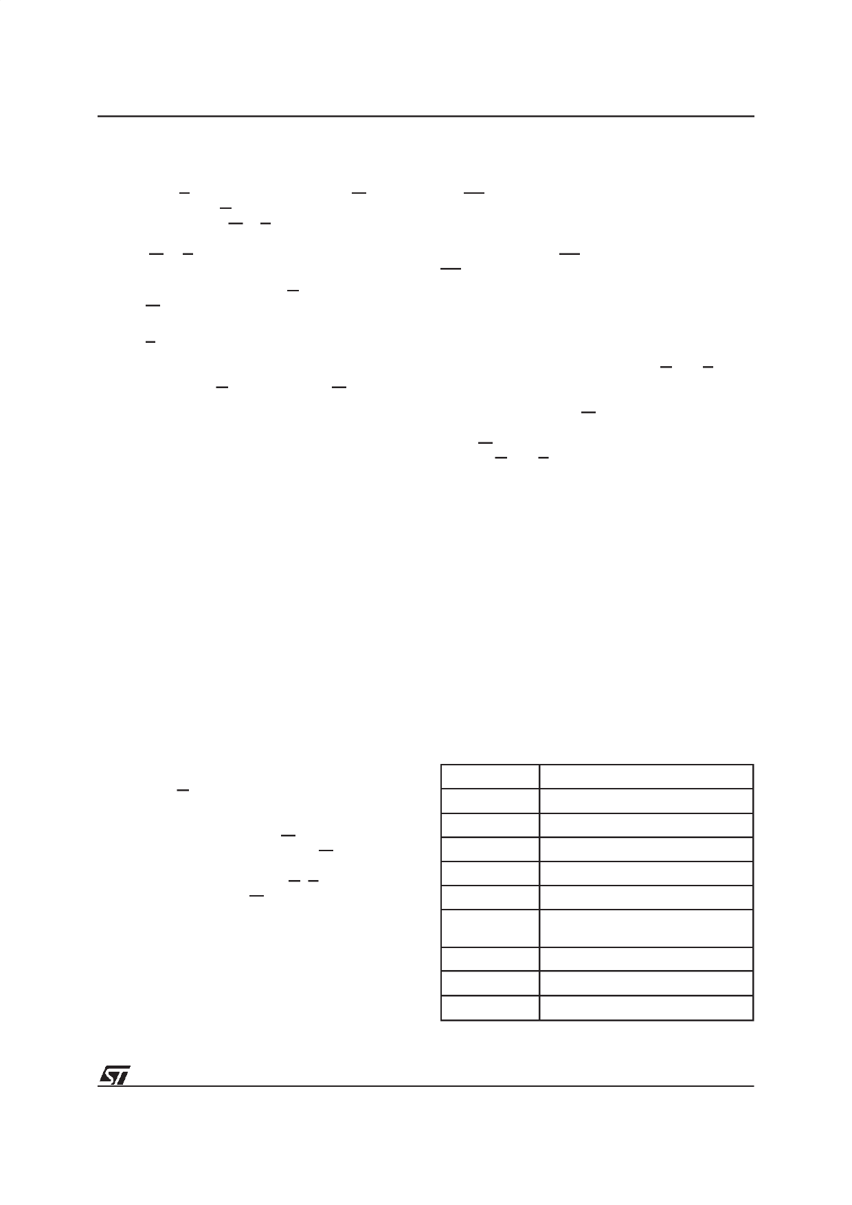
Table 7. Commands
Hex Code
Command
00h
Invalid/Reserved
10h
Chip Erase Confirm
20h
Reserved
30h
Block Erase Resume/Confirm
80h
Set-up Erase
90h
Read Electronic Signature/
Block Protection Status
A0h
Program
B0h
Erase Suspend
F0h
Read Array/Reset
7/29
Share Link: 