M29W400 データシートの表示(PDF) - STMicroelectronics
部品番号
コンポーネント説明
メーカー
M29W400
STMicroelectronics

M29W400 Datasheet PDF : 34 Pages
| |||
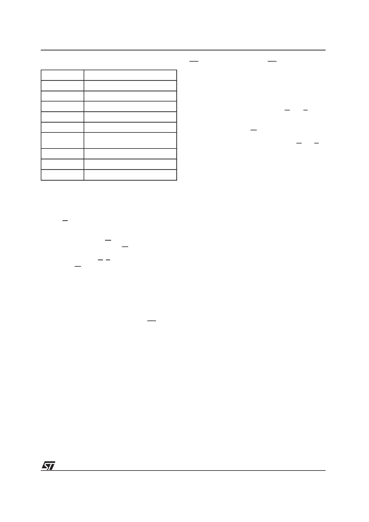
M29W400T, M29W400B
Table 7. Commands
Hex Code
00h
10h
Command
Invalid/Reserved
Chip Erase Confirm
20h
Reserved
30h
Block Erase Resume/Confirm
80h
Set-up Erase
90h
Read Electronic Signature/
Block Protection Status
A0h
Program
B0h
Erase Suspend
F0h
Read Array/Reset
Block Protection. Each block can be separately
protected against Program or Erase on program-
ming equipment. Block protection provides addi-
tional data security, as it disables all program or
erase operations.This mode is activatedwhen both
A9 and G are raised to VID and an address in the
block is applied on A12-A17. The Block Protection
algorithm is shown in Figure 14. Block protectionis
initiated on the edge of W falling to VIL. Then after
a delay of 100µs, the edge of W rising to VIH ends
the protection operations. Block protection verify is
achieved by bringing G, E, A0 and A6 to VIL and A1
to VIH, while W is at VIH and A9 at VID. Under these
conditions, reading the data output will yield 01h if
the block defined by the inputs on A12-A17 is
protected. Any attempt to program or erase a pro-
tected block will be ignored by the device.
Block Temporary Unprotection. Any previously
protected block can be temporarily unprotected in
order to change stored data. The temporary unpro-
tection mode is activated by bringing RP to VID.
During the temporary unprotection mode the pre-
viously protected blocks are unprotected. A block
can be selected and data can be modified by
executing the Eraseor Program instruction with the
RP signal held at VID. When RP is returned to VIH,
all the previously protected blocks are again pro-
tected.
Block Unprotection. All protected blocks can be
unprotected on programming equipment to allow
updating of bit contents. All blocks must first be
protected before the unprotectionoperation. Block
unprotection is activated when A9, G and E are at
VID and A12, A15 at VIH. The Block Unprotection
algorithm is shown in Figure 15. Unprotection is
initiated by the edge of W fallingto VIL. Aftera delay
of 10ms, the unprotection operation will end. Un-
protection verify is achieved by bringing G and E to
VIL while A0 is at VIL, A6 and A1 are at VIH and A9
remains at VID. In these conditions, reading the
output data will yield 00h if the block defined by the
inputs A12-A17 has been succesfully unprotected.
Each block must be separatelyverified by giving its
address in order to ensure that it has been unpro-
tected.
INSTRUCTIONS AND COMMANDS
The Command Interface latches commands writ-
ten to the memory. Instructions are made up from
one or more commands to perform Read Memory
Array, Read Electronic Signature, Read Block Pro-
tection, Program, Block Erase, Chip Erase, Erase
Suspend and Erase Resume. Commands are
made of address and data sequences. The in-
structions require from 1 to 6 cycles, the first or first
three of which are always write operations used to
initiate the instruction. They are followed by either
further write cycles to confirm the first command or
execute the command immediately. Command se-
quencing must be followed exactly. Any invalid
combination of commands will reset the device to
Read Array. The increased number of cycles has
been chosen to assure maximum data security.
Instructions are initialised by two initial Coded cy-
cles which unlock the Command Interface. In addi-
tion, for Erase, instruction confirmation is again
preceded by the two Coded cycles.
9/34
Share Link: