M5913B1 データシートの表示(PDF) - STMicroelectronics
部品番号
コンポーネント説明
メーカー
M5913B1 Datasheet PDF : 17 Pages
| |||
M5913
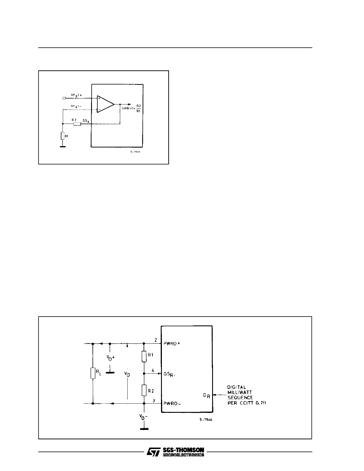
Figure 3: Transmit Filter Gain Adjustment.
an internal sample and hold capacitor. This sam-
ple is then transferred to the receive filter.
Receive Filter
The receive section of the filter provides pass-
band flatness and stopband rejection which fulfills
both the AT&T D3/D4 specification and CCITT
recommendation G.712. The filter contains the re-
quired compensation for the (sin X)/X response of
such decoders. The receive filter characteristics
and specifications are shown in the relative table.
Encoding
The encoder internally samples the output of the
transmit filter and holds each sample on an inter-
nal sample and hold capacitor.
The encoder then performs an analog to digital
conversion on a switched capacitor array. Digital
data representing the sample is transmitted on
the first eight data clock bits of the next frame.
An on-chip autozero circuit corrects for DC-offset
on the input signal to the encoder. This autozero
circuit uses the sign bit averaging technique. In
this way, all DC offset is removed from the en-
coder input waveform.
RECEIVE OPERATION
Decoding
The PCM word at the DR lead is serially fetched
on the first eight data clock bits of the frame.
A D/A conversion is performed on the digital word
and the corresponding analog sample is held on
Figure 4: Gain Setting Configuration.
Receive Output Power Amplifiers
A balanced output amplifier is provided in order to
allow maximum flexibility in output configuration.
Either of the two outputs can be used single
ended (referenced to GRDA) to drive single
ended loads. Alternatively, the differential output
will drive a bridged load directly. The output stage
is capable of driving loads as low as 300 ohms
single ended to a level of 12dBm or 600 ohms dif-
ferentially to a level of 15dBm.
The receive channel transmission level may be
adjusted between specified limits by manipulation
of the GSR input. GSR is internally connected to
an analog gain setting network. When GSR is
strapped to PWRO–, the receive level is mini-
mized; when it is tied to PWRO+, the level is mini-
mized. The output transmission level interpolates
between 0 and -12dB as GSR is interpolated
(with potentiometer) between PWRO- and
PWRO+. The use of the output gain set is illus-
trated in figure 4.
Transmission levels are specified relative to the
receive channel output under digital milliwatt con-
ditions, that is, when the digital input at DR is the
eight-code sequence specified in CCITT recom-
mendation G.711.
6/17
Share Link: 