M7085(2012) データシートの表示(PDF) - Unisonic Technologies
部品番号
コンポーネント説明
メーカー
M7085 Datasheet PDF : 7 Pages
| |||
M7085
CMOS IC
APPLICATION INFORMATION
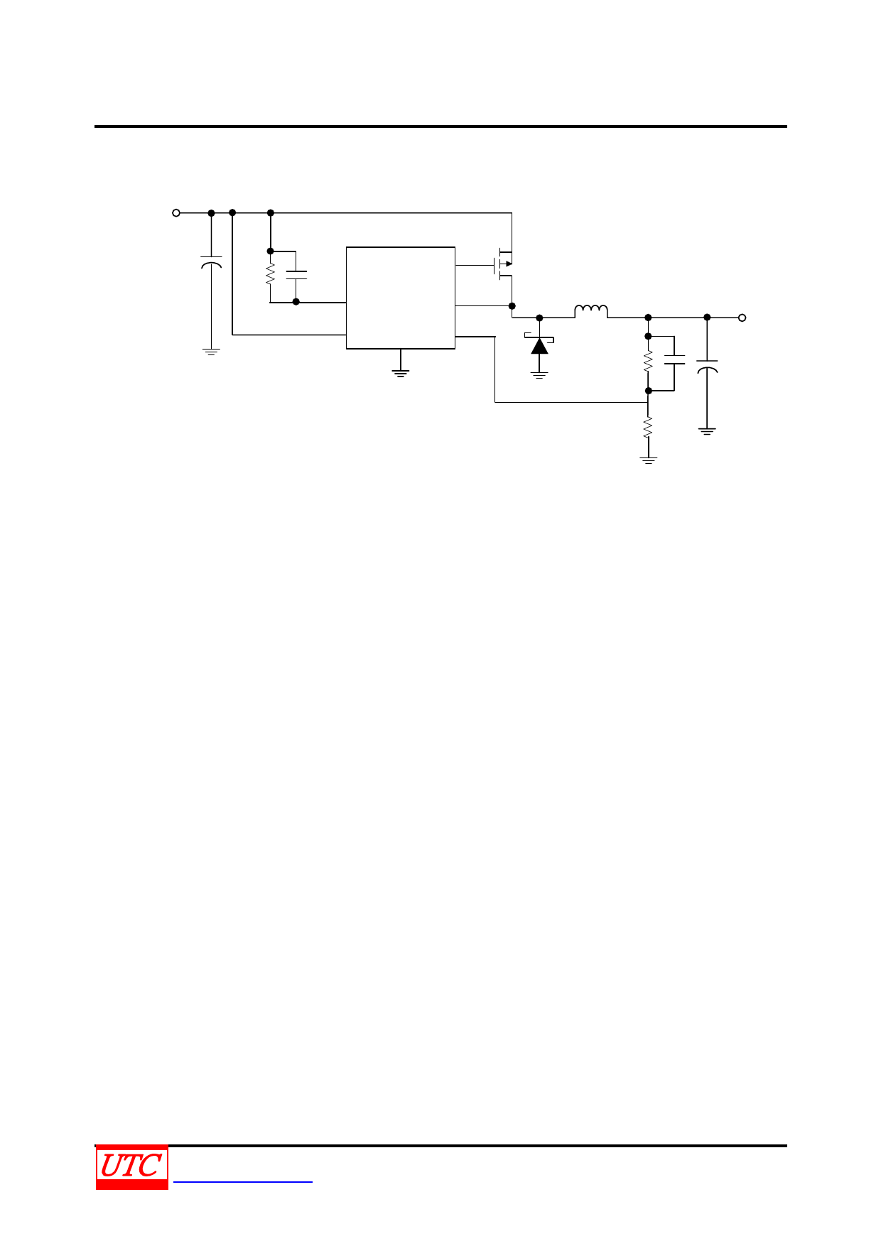
Setting the output voltage
Select an output voltage between 1.24V and VIN by connecting FB to a resistive voltage-divider between VOUT
and GND (see the Typical Operating Circuit). Choose R2 for a reasonable bias current in the resistive divider. A wide
range of resistor values is acceptable.
R1, R2 is given by:
VOUT = 1.240* (R1 + R2) / R2
Setting over current protection threshold by the RDS(ON) of the P-Channel
The UTC M7085 has a cycle-by-cycle current limit. Current limit is sensed across the VDS of the P-Channel or
across an additional sense resistor. When current limit is activated, the UTC M7085 turns off the external P-Channel
for a period of 9μs(typical). The current limit is adjusted by an external resistor, RADJ.
The current limit circuit is composed of the ISENSE comparator and the one-shot pulse generator. The positive input
of the ISENSE comparator is the ADJ pin. An internal 5.5µA current sink creates a voltage across the external RADJ
resistor. This voltage is compared to the voltage across the P-Channel or sense resistor. The ADJ voltage can be
calculated as follows:
VADJ = VIN - (RADJ * 3.0μA)
Where 3.0μA is the minimum ICL(ADJ) value.
The negative input of the ISENSE comparator is the ISENSE pin that should be connected to the drain of the external
P-Channel. The inductor current is determined by sensing the VDS. It can be calculated as follows.
VISENSE = VIN - (RDS(ON) * IIND_PEAK) = VIN - VDS
CADJ
5.5µA
ADJ
5
ISENSE
COMP
RADJ
1
VIN
ISENSE
VDS
Fig. 1 Current Sensing by VDS
The current limit is activated when the voltage at the ADJ pin exceeds the voltage at the ISENSE pin. The ISENSE
comparator triggers the 9μs one shot pulse generator forcing the driver to turn the P-Channel off. The driver turns
the P-Channel back on after 9μs. If the current has not reduced below the set threshold, the cycle will repeat
continuously.
A filter capacitor, CADJ, should be placed as shown in Fig. 1 CADJ filters unwanted noise so that the ISENSE
comparator will not be accidentally triggered. A value of 100pF to 1nF is recommended in most applications. Higher
values can be used to create a soft-start function. The current limit comparator has approximately 100ns of blanking
time. This ensures that the P-Channel is fully on when the current is sensed. However, under extreme conditions
such as cold temperature, some P-Channels may not fully turn on within the blanking time. In this case, the current
limit threshold must be increased. If the current limit function is used, the on time must be greater than 100ns. Under
low duty cycle operation, the maximum operating frequency will be limited by this minimum on time.
UNISONIC TECHNOLOGIES CO., LTD
www.unisonic.com.tw
5 of 7
QW-R502-092, Ba
Share Link: 