MAX3097ECSE гғҮгғјгӮҝгӮ·гғјгғҲгҒ®иЎЁзӨәпјҲPDFпјү - Maxim Integrated
йғЁе“Ғз•ӘеҸ·
гӮігғігғқгғјгғҚгғігғҲиӘ¬жҳҺ
гғЎгғјгӮ«гғј
MAX3097ECSE
Maxim Integrated

MAX3097ECSE Datasheet PDF : 16 Pages
| |||
Вұ15kV ESD-Protected, 32Mbps, 3V/5V,
Triple RS-422/RS-485 Receivers with Fault Detection
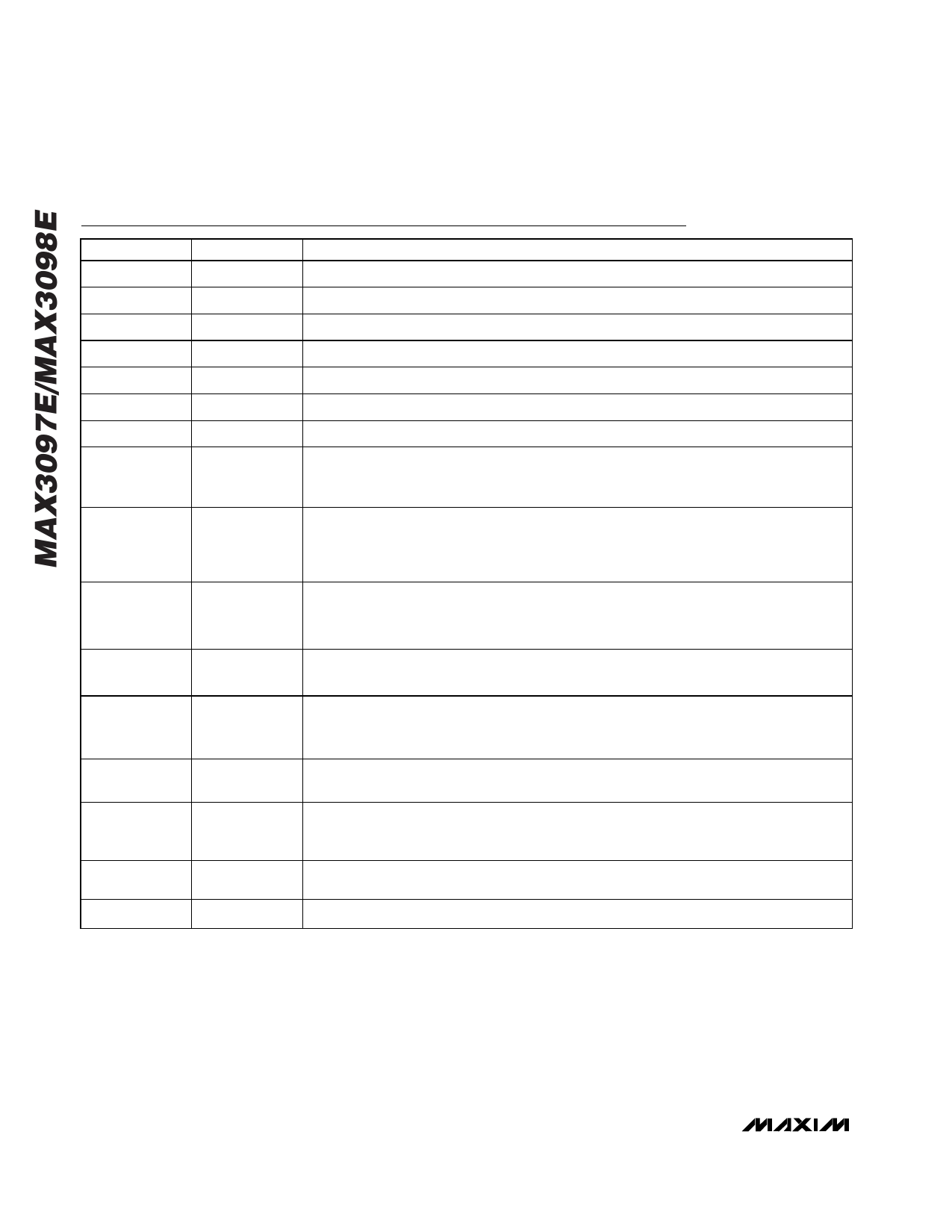
Pin Description
PIN
NAME
FUNCTION
1
A
Noninverting Receiver A Input
2
A
Inverting Receiver A Input
3
B
Noninverting Receiver B Input
4
B
Inverting Receiver B Input
5
Z
Noninverting Receiver Z Input
6
Z
Inverting Receiver Z Input
7
GND
Ground
Programmable Delay Terminal. Connect a capacitor from DELAY to GND to set the
8
DELAY
ALARMD output delay time. To obtain a minimum delay, leave DELAY unconnected. See
Capacitance vs. ALARMD Output Delay in the Typical Operating Characteristics.
Delayed Fault Output. This output is the logic OR of ALARMA, ALARMB, and ALARMZ.
9
ALARMD
Place a capacitor from the DELAY pin to GND to set the delay (see Setting Delay Time). A
high logic level indicates a fault condition on at least one receiver input pair. A low level on
this pin indicates no fault condition is present.
Z Receiver Output. If VZ - VZ вүҘ +200mV, OUTZ will be high. If VZ - V Z вүӨ -200mV, OUTZ will
10
OUTZ
be low. If Z or Z exceeds the receiverвҖҷs input common-mode voltage range, the ALARMZ
output will be high and OUTZ will be indeterminate.
11
ALARMZ
Z Fault Output. When ALARMZ is high, OUTZ is indeterminate. Tables 1 and 2 show all the
possible states for which an alarm is set.
B Receiver Output. If VB - V B вүҘ +200mV, OUTB will be high. If VB - V B вүӨ -200mV, OUTB will
12
OUTB
be low. If B or B exceeds the input receiverвҖҷs common-mode voltage range, the ALARMB
output will be high and OUTB will be indeterminate.
13
ALARMB
B Fault Output. When ALARMB is high, OUTB is indeterminate. Tables 1 and 2 show all the
possible states for which an alarm is set.
A Receiver Output. If VA - V A вүҘ +200mV, OUTA will be high. If VA - V A вүӨ -200mV, OUTA will
14
OUTA
be low. If A or A exceeds the receiverвҖҷs input common-mode voltage range, the ALARMA
output will be high and OUTA will be indeterminate.
15
ALARMA
A Fault Output. When ALARMA is high, OUTA is indeterminate. Tables 1 and 2 show all the
possible states for which an alarm is set.
16
VCC
Power Supply
6 _______________________________________________________________________________________
Share Link: