MAX3760(1998) データシートの表示(PDF) - Maxim Integrated
部品番号
コンポーネント説明
メーカー
MAX3760
(Rev.:1998)
(Rev.:1998)
Maxim Integrated

MAX3760 Datasheet PDF : 8 Pages
| |||
622Mbps, Low-Noise Transimpedance
Preamplifier for LAN and WAN Optical Receivers
ABSOLUTE MAXIMUM RATINGS
VCC ........................................................................-0.5V to +7.0V
Continuous Current
IN, FILTER ..........................................................-5mA to +5mA
OUT+, OUT-...................................................-25mA to +25mA
Voltage at INREF ...................................................-0.5V to +0.5V
Voltage at COMP........................................-0.5V to (VCC + 0.5V)
Continuous Power Dissipation (TA = +85°C)
SO (derate 5.88mW/°C above +85°C) ..........................383mW
Storage Temperature Range .............................-65°C to +160°C
Lead Temperature (soldering, 10sec) .............................+300°C
Operating Junction Temperature Range (die) .....-55°C to +150°C
Processing Temperature (die) .........................................+400°C
Stresses beyond those listed under “Absolute Maximum Ratings” may cause permanent damage to the device. These are stress ratings only, and functional
operation of the device at these or any other conditions beyond those indicated in the operational sections of the specifications is not implied. Exposure to
absolute maximum rating conditions for extended periods may affect device reliability.
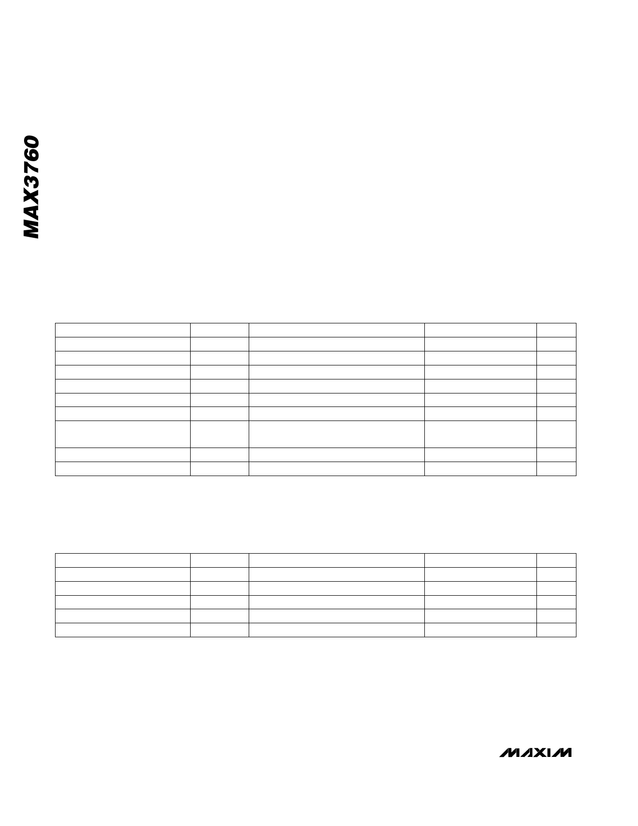
DC ELECTRICAL CHARACTERISTICS
(VCC = +4.5V to +5.5V, COMP = GND, 100Ω load between OUT+ and OUT-, TA = -40°C to +85°C, unless otherwise noted. Typical
values are at VCC = +5.0V, TA = +25°C.) (Note 1)
PARAMETER
Input Bias Voltage
Supply Current
Small-Signal Transimpedance
Output Common-Mode Level
Differential Output Offset
Output Impedance (per side)
Maximum Differential
Output Voltage
FILTER Resistance
Power-Supply Rejection Ratio
SYMBOL
VIN
ICC
z21
CONDITIONS
Input = open
Input = open
Differential output, input <10µA
VOS
ZOUT
VOUT(MAX)
RFILTER
PSRR
IIN = 500µA, COMP = open
IIN = 500µA, total peak-to-peak,
differential signal
f < 1MHz, referred to output
MIN TYP MAX
0.8
0.95
20
30
5.2
6.5
7.8
VCC - 2.0
-25
25
40
50
60
UNITS
V
mA
kΩ
V
mV
Ω
550
950
mV
800 1000 1200
Ω
20
45
dB
Note 1: Dice are tested at TA = +25°C.
AC ELECTRICAL CHARACTERISTICS
(VCC = +4.5V to +5.5V, COMP = open, CIN = 0.75pF, outputs terminated differentially into 100Ω, 8-pin SO package in MAX3760
EV kit, TA = +25°C, unless otherwise noted. Typical values are at VCC = +5V.) (Notes 2, 3)
PARAMETER
Small-Signal Bandwidth
Low-Frequency Cutoff
Pulse-Width Distortion
RMS Noise Referred to Input
Data-Dependent Jitter
SYMBOL
BW
PWD
in
DDJ
CONDITIONS
20µA average input current
(Note 4)
CIN = 0.75pF (Notes 3, 5)
MIN TYP MAX UNITS
455
565
MHz
50
kHz
75
200
ps
73
93.5
nA
200
ps
Note 2: AC characteristics are guaranteed by design and characterization.
Note 3: CIN is the source capacitance presented to the die. Includes package parasitic, photo diode, and parasitic interconnect
capacitance.
Note 4: Input is a 622Mbps 1-0 pattern, signal amplitude = 0 to 1mA, extinction ratio (re) = 10.
Note 5: Measured with a 4-pole, 470MHz Bessel filter.
2 _______________________________________________________________________________________
Share Link: