MAX365CSE(2001) データシートの表示(PDF) - Maxim Integrated
部品番号
コンポーネント説明
メーカー
MAX365CSE Datasheet PDF : 12 Pages
| |||
Precision, Quad, SPST Analog Switches
__________Applications Information
Application Hints
1. Switches are open when power is off.
2. IN_, COM_, NO_, and NC_ should not exceed V+ or
V-, even with the power off.
3. Switch leakage is from each analog switch terminal
to V+ or V-, not to the other switch terminal.
Operation with Supply Voltages
Other than ±15VO
The main limitation of supply voltages other than ±15V is
reduction in the analog signal range. The MAX364/MAX365
switches operate with ±5V to ±20V bipolar supplies. The
Typical Operating Characteristics graphs show typical on
resistance for ±15V, ±10V, and ±5V supplies. Switching
times increase by a factor of two or more for ±5V opera-
tion. The MAX364/MAX365 operate from unipolar sup-
plies of +10V to +24V. Both parts can be powered from a
single +10V to +24V supply, as well as from unbalanced
supplies, such as +24V and -5V. Connect V- to 0V when
operating with a single supply. VL must be connected to
+5V to be TTL compatible or to V+ for CMOS logic input
levels.
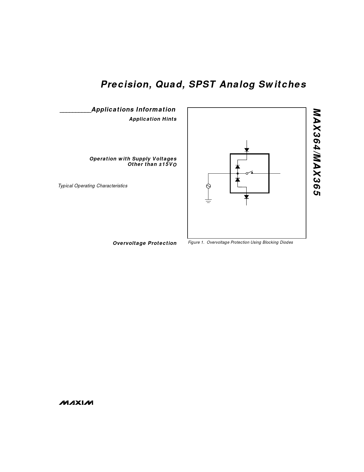
Overvoltage Protection
Proper power-supply sequencing is recommended for
all CMOS devices. It is important not to exceed the
absolute maximum ratings, because stresses beyond
those listed may cause permanent damage to the
devices. Always sequence V+ on first, followed by VL,
V-, and logic inputs. If power-supply sequencing is not
possible, protect the devices from overvoltage by
V+
NO_
Vg
V-
COM_
Figure 1. Overvoltage Protection Using Blocking Diodes
adding two small signal diodes in series with the supply
pins (Figure 1). Adding the diodes reduces the analog
signal range to 1V below V+ and 1V below V-, but low
switch resistance and low leakage characteristics are
unaffected. Device operation is unchanged, and the
difference between V+ to V- should not exceed +44V.
_______________________________________________________________________________________ 7
Share Link: 