MAX5941BCSE(2003) データシートの表示(PDF) - Maxim Integrated
部品番号
コンポーネント説明
メーカー
MAX5941BCSE
(Rev.:2003)
(Rev.:2003)
Maxim Integrated

MAX5941BCSE Datasheet PDF : 24 Pages
| |||
IEEE 802.3af-Compliant Power-Over-Ethernet
Interface/PWM Controller for Power Devices
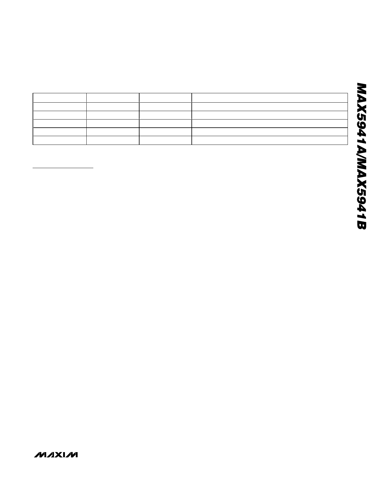
Table 1. PD Power Classification/RCL Selection
CLASS
USAGE
0
Default
1
Optional
2
Optional
3
Optional
4
Not allowed
*Class 4 reserved for future use.
RCL (Ω)
10k
732
392
255
178
MAXIMUM POWER USED BY PD (W)
0.44 to 12.95
0.44 to 3.84
3.84 to 6.49
6.49 to 12.95
Reserved*
Detailed Description
The MAX5941A/MAX5941B integrate a complete power
IC for powered devices (PDs) in a power-over-ethernet
(PoE) system. The MAX5941A/MAX5941B provide PD
interface and a compact DC-DC PWM controller suitable
for flyback and forward converters in either isolated or
nonisolated designs.
The MAX5941A/MAX5941B powered device (PD) inter-
face complies with the IEEE 802.3af standard, providing
the PD with a detection signature, a classification signa-
ture, and an integrated isolation switch with programma-
ble inrush current control. These devices also feature
power-mode undervoltage lockout (UVLO) with wide hys-
teresis, and power-good status outputs.
An integrated MOSFET provides PD isolation during
detection and classification. The MAX5941A/MAX5941B
guarantee a leakage current offset of less than 10µA dur-
ing the detection phase. A programmable current limit
prevents high inrush current during power-on. The
devices feature power-mode UVLO with wide hysteresis
and long deglitch time to compensate for twisted-pair
cable resistive drop and to ensure glitch-free transition
between detection, classification, and power-on/off phas-
es. The MAX5941A/MAX5941B provide both active-high
(PGOOD) and active-low (PGOOD) outputs. Both
devices offer an adjustable UVLO threshold with a
default value compliant to the IEEE 802.3af standard.
The MAX5941A/MAX5941B are designed to work with or
without an external diode bridge in front of the PD.
Use the MAX5941A/MAX5941B PWM current-mode con-
trollers to design flyback- or forward-mode power sup-
plies. Current-mode operation simplifies control-loop
design while enhancing loop stability. An internal high-
voltage startup regulator allows the device to connect
directly to the input supply without an external startup
resistor. Current from the internal regulator starts the con-
troller. Once the tertiary winding voltage is established,
the internal regulator is switched off and bias current for
running the PWM controller is derived from the tertiary
winding. The internal oscillator is set to 275kHz and
trimmed to ±10%. This permits the use of small magnetic
components to minimize board space. Both the
MAX5941A and MAX5941B can be used in power sup-
plies providing multiple output voltages. A functional dia-
gram of the PWM controller is shown in Figure 4. Typical
applications circuits for forward and flyback topologies
are shown in Figure 5 and Figure 6, respectively.
Powered Device Interface
Operating Modes
The powered device (PD) front-end section of the
MAX5941A/MAX5941B operates in three different modes:
PD detection signature, PD classification, and PD power,
depending on its input voltage (VIN = GND - VEE). All
voltage thresholds are designed to operate with or with-
out the optional diode bridge while still complying with
the IEEE 802.3af standard (see Application Circuit 1).
Detection Mode (1.4V ≤ VIN ≤ 10.1V)
In detection mode, the power source equipment (PSE)
applies two voltages on VIN in the range of 1.4V to
10.1V (1V step minimum), and then records the current
measurements at the two points. The PSE then com-
putes ∆V/∆I to ensure the presence of the 25.5kΩ sig-
nature resistor. In this mode, most of the MAX5941A/
MAX5941B internal circuitry is off and the offset current
is less than 10µA.
If the voltage applied to the PD is reversed, install pro-
tection diodes on the input terminal to prevent internal
damage to the MAX5941A/MAX5941B (see Figure 7).
Since the PSE uses a slope technique (∆V/∆I) to calcu-
late the signature resistance, the DC offset due to the
protection diodes is subtracted and does not affect the
detection process.
Classification Mode (12.6V ≤ VIN ≤ 20V)
In the classification mode, the PSE classifies the PD
based on the power consumption required by the PD.
This allows the PSE to efficiently manage power distribu-
tion. The IEEE 802.3af standard defines five different
classes as shown in Table 1. An external resistor (RCL)
connected from RCL to VEE sets the classification current.
______________________________________________________________________________________ 11
Share Link: