MAX6304ESA データシートの表示(PDF) - Maxim Integrated
部品番号
コンポーネント説明
メーカー
MAX6304ESA Datasheet PDF : 12 Pages
| |||
+5V, Low-Power µP Supervisory Circuits
with Adjustable Reset/Watchdog
VIN
VCC
VCC
VCC
R1
RESET IN
VCC
R2
MAX6301
0.1µF
MAX6302
MAX6303
MAX6304
MAX6302
VCC
RESET
*
WDI
WDS
GND
80C51
VCC
RST
I/O
I/O
I/O
GND
( ) VRST = 1.22
R1 + R2
R2
*THREE-STATE LEAKAGE MUST BE < 10µA.
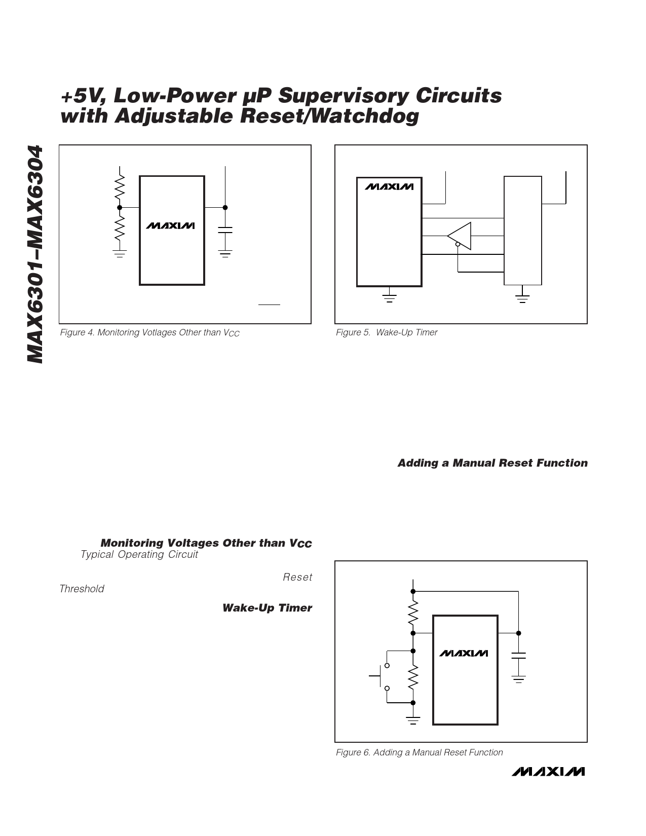
Figure 4. Monitoring Votlages Other than VCC
Figure 5. Wake-Up Timer
with CSRT in pF and tRP in µs. CSRT must be a low-leak-
age (< 10nA) type capacitor. Ceramic is recommended.
The watchdog timeout period is adjustable to accom-
modate a variety of µP applications. With this feature,
the watchdog timeout can be optimized for software
execution. The programmer can determine how often
the watchdog timer should be serviced. Adjust the
watchdog timeout period (tWD) by connecting a specif-
ic value capacitor (CSWT) between SWT and ground
(Figure 3). For normal-mode operation, calculate the
watchdog timeout capacitor as follows:
CSWT = tWD / 2.67
where CSWT is in pF and tWD is in µs. CSWT must be a
low-leakage (< 10nA) type capacitor. Ceramic is
recommended.
Monitoring Voltages Other than VCC
The Typical Operating Circuit monitors VCC. Voltages
other than VCC can easily be monitored, as shown in
Figure 4. Calculate VRST as shown in the Reset
Threshold section.
watchdog timeout period ends, a reset is applied on
the 80C51, waking it up to perform tasks. While the µP
is performing tasks, the 80C51 pulls WDS low (select-
ing normal mode), and the MAX6302 monitors the µP
for hang-ups. When the µP finishes its tasks, it puts
itself back into sleep mode, drives WDS high, and
starts the cycle over again. This is a power-saving tech-
nique, since the µP is operating only part of the time
and the MAX6302 has very low quiescent current.
Adding a Manual Reset Function
A manual reset option can easily be implemented by con-
necting a normally open momentary switch in parallel with
R2 (Figure 6). When the switch is closed, the voltage on
RESET IN goes to zero, initiating a reset. When the
switch is released, the reset remains asserted for the
reset timeout period and then is cleared. The pushbut-
ton switch is effectively debounced by the reset timer.
VCC
Wake-Up Timer
In some applications, it is advantageous to put a µP
into sleep mode, periodically wake it up to perform
checks and/or tasks, then put it back into sleep mode.
The MAX6301 family of supervisors can easily accom-
modate this technique. Figure 5 illustrates an example
using the MAX6302 and an 80C51.
In Figure 5, just before the µC puts itself into sleep
mode, it pulls WDS high. The µC’s I/O pins maintain
their logic levels while in sleep mode and WDS remains
high. This places the MAX6302 in extended mode,
increasing the watchdog timeout 500 times. When the
R1
RESET IN
VCC
0.1µF
MAX6301
R2
MAX6302
MAX6303
MAX6304
Figure 6. Adding a Manual Reset Function
8 _______________________________________________________________________________________
Share Link: 