MC100E196FNG データシートの表示(PDF) - ON Semiconductor
部品番号
コンポーネント説明
メーカー
MC100E196FNG Datasheet PDF : 12 Pages
| |||
MC10E196, MC100E196
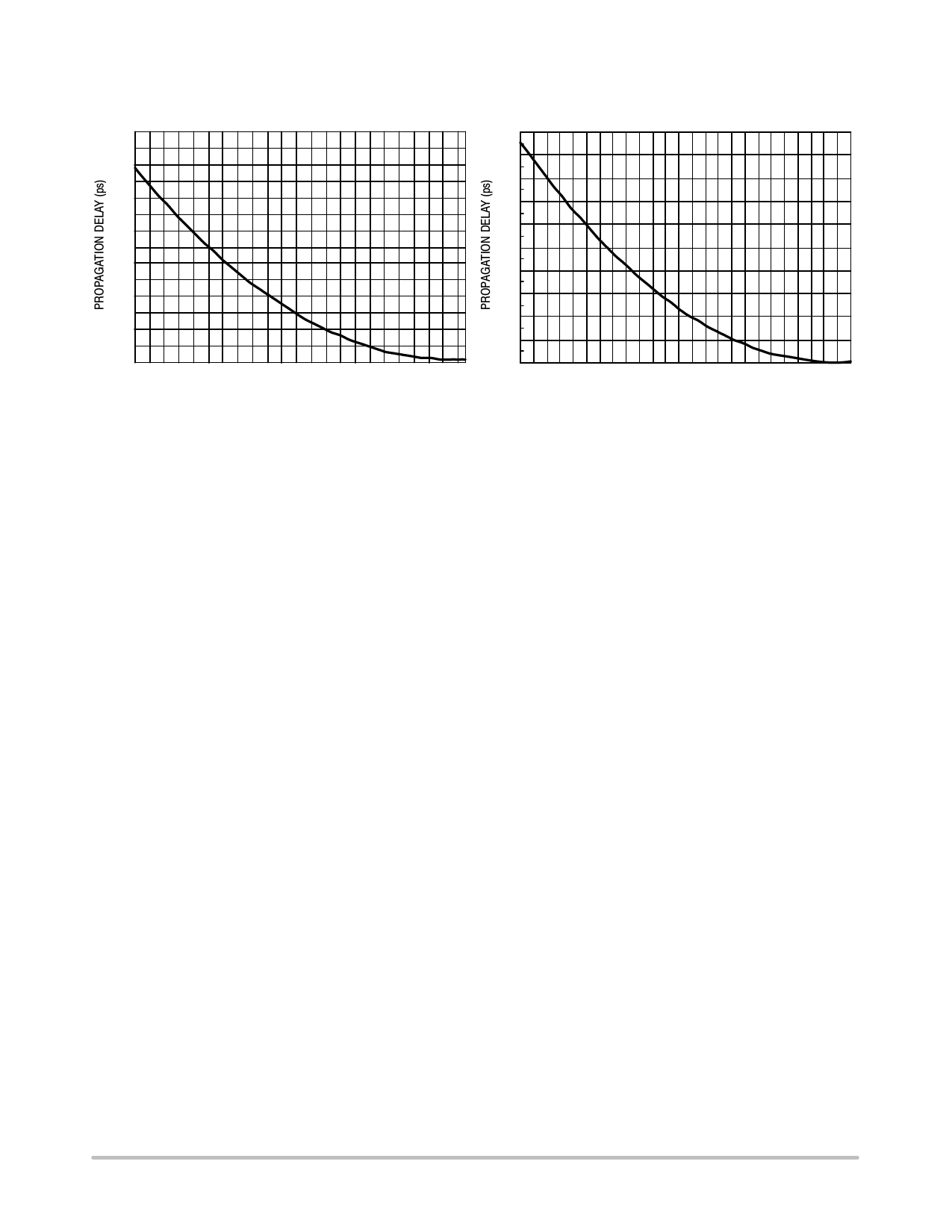
ANALOG INPUT CHARACTERISTICS
FTUNE = VCC to VEE
140
100
90
120
80
100
70
60
80
50
60
40
40
30
20
20
10
0
−4.5
−3.5
−2.5
−1.5
−0.5
0
−5
−4
−3
−2
−1
0
FTUNE VOLTAGE (V)
FTUNE VOLTAGE (V)
Propagation Delay versus FTUNE Voltage
(100E196)
Propagation Delay versus FTUNE Voltage
(10E196)
USING THE FTUNE ANALOG INPUT
The analog FTUNE pin on the E196 device is intended to
add more delay in a tunable gate to enhance the 20 ps
resolution capabilities of the fully digital E195. The level of
resolution obtained is dependent on the number of
increments applied to the appropriate range on the FTUNE
pin.
To provide this further level of resolution (See Logic
Diagram), the FTUNE pin must be capable of adjusting the
additional delay finer than the 20 ps digital resolution. From
the provided graphs one sees that this requirement is easily
achieved as over the entire FTUNE voltage range a 100 ps
additional delay can be achieved. This extra analog range
ensures that the FTUNE pin will be capable even under
worst case conditions of covering the digital resolution.
Typically the analog input will be driven by an external DAC
to provide a digital control with very fine analog output
steps. The final resolution of the device will be dependent on
the width of the DAC chosen.
To determine the voltage range necessary for the FTUNE
input, the graphs provided should be used. As an example if
a tuning range of 40 ps is selected to cover worst case
conditions and ensure coverage of the digital range, from the
100E196 graph a voltage range of −3.25 V to −4.0 V would
be necessary on the FTUNE pin. Obviously there are
numerous voltage ranges which can be used to cover a given
delay range, users are given the flexibility to determine
which one best fits their designs.
Cascading Multiple E196’s
To increase the programmable range of the E196 internal
cascade circuitry has been included. This circuitry allows for
the cascading of multiple E196’s without the need for any
external gating. Furthermore this capability requires only
one more address line per added E196. Obviously cascading
multiple PDC’s will result in a larger programmable range,
however, this increase is at the expense of a longer minimum
delay.
Figure 3 illustrates the interconnect scheme for
cascading two E196’s. As can be seen, this scheme can
easily be expanded for larger E196 chains. The D7 input of
the E196 is the cascade control pin. With the interconnect
scheme of Figure 3 when D7 is asserted it signals the need
for a larger programmable range than is achievable with a
single device.
An expansion of the latch section of the block diagram is
pictured below. Use of this diagram will simplify the
explanation of how the cascade circuitry works. When D7
of chip #1 above is low the cascade output will also be low
while the cascade bar output will be a logical high. In this
condition the SET MIN pin of chip #2 will be asserted and
thus all of the latches of chip #2 will be reset and the device
will be set at its minimum delay. Since the RESET and SET
inputs of the latches are overriding any changes on the
A0−A6 address bus will not affect the operation of chip #2.
Chip #1 on the other hand will have both SET MIN and
SET MAX de-asserted so that its delay will be controlled
entirely by the address bus A0−A6. If the delay needed is
greater than can be achieved with 31.75 gate delays
(1111111 on the A0−A6 address bus) D7 will be asserted to
signal the need to cascade the delay to the next E196 device.
When D7 is asserted the SET MIN pin of chip #2 will be
de-asserted and the delay will be controlled by the A0−A6
address bus. Chip #1 on the other hand will have its SET
MAX pin asserted resulting in the device delay to be
independent of the A0−A6 address bus.
http://onsemi.com
7
Share Link: 