MC13001X データシートの表示(PDF) - Motorola => Freescale
部品番号
コンポーネント説明
メーカー
MC13001X Datasheet PDF : 10 Pages
| |||
MC13001X MC13007X
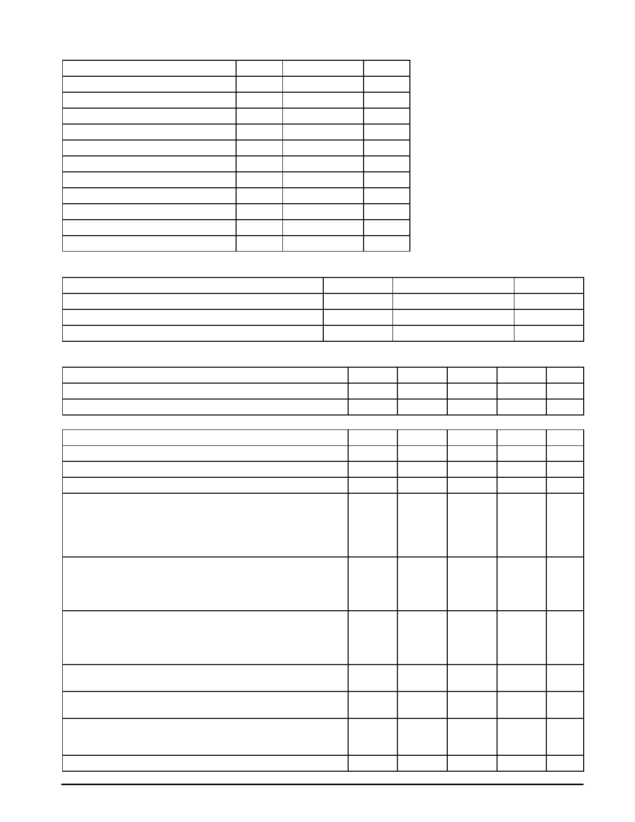
MAXIMUM RATINGS (TA = 25°C, unless otherwise noted.)
Rating
Symbol
Value
Power Supply Voltage – Pin 18
Power Dissipation
Horizontal Driver Current – Pin 17
RF AGC Current – Pin 11
Video Detector Current – Pin 24
Vertical Driver Current – Pin 22
Auxiliary Regulator Current – Pin 19
Thermal Resistance Junction–to–Case
Maximum Junction Temperature
Storage Temperature Range
Operating Temperature Range
VCC
PD
Ihor
IRFAGC
IVID
Ivert
Ireg
RθJC
TJ
Tstg
TA
+16
1.0
–20
20
5.0
5.0
35
60
150
–65 to + 150
0° to + 70
Unit
Vdc
W
mA
mA
mA
mA
mA
°C/W
°C
°C
°C
RECOMMENDED OPERATING CONDITIONS
Rating
Horizontal Output Drive Current
RF AGC Current
Regulator Current
ELECTRICAL CHARACTERISTICS (VCC = 11.3 V, TA = 25°C)
Characteristics
Power Supply Current (Pins 18, 19)
Regulator Voltage (Pin 19)
HORIZONTAL SPECIFICATIONS
Oscillator Frequency (Nominal) (Pin 12)
Oscillator Sensitivity
Startup Frequency (I18 = 4.0 mA)
Oscillator Temperature Stability (0 ≤ TA ≤ 75°C)
Phase Detector 1 (Charge/Discharge Current)
(Non–Standard Frame)
(Standard Frame)
Phase Detector 2
(Charge/Discharge Current)
Phase Detector 1
(Output Voltage Limits)
Phase Detector 2
(Output Voltage Limits)
Phase Detector 1
(Leakage Current)
Phase Detector 2
(Leakage Current)
Horizontal Delay Range
(Sync to Flyback)
Horizontal Output Saturation Voltage
(I17 = 15 mA)
Phase–Detector 1 (Gain Constant)
(Out–of–Lock)
(In–Lock)
Horizontal Pull–In Range
Symbol
Ihor
IRFAGC
Ireg
Value
≤10
≤10
≤20
Symbol
Min
ICC
44
Vreg
7.2
fhor(NOM)
13
–
fhor
–10
–
–
Iφ1
–
–
Vφ2
–
Vφ1
–
Vφ1
–
–
–
–
–
V17(sat)
–
Typ
–
8.2
–
230
–
50
±900
±400
+1.0
–0.6
7.5 (max)
2.5 (min)
7.7 (max)
1.5 (min)
–
–
18 (max)
5.0 (min)
–
–
–
±500
5.0
10
±750
Unit
mA
mA
mA
Max
Unit
76
mA
8.8
Vdc
19
kHz
–
Hz/µA
+10
%
–
Hz
–
µA
–
–
mA
–
Vdc
–
2.0
µA
3.0
–
µs
–
0.3
Vdc
µA/µs
–
–
–
Hz
2
MOTOROLA ANALOG IC DEVICE DATA
Share Link: 