MC1403BP1G データシートの表示(PDF) - ON Semiconductor
部品番号
コンポーネント説明
メーカー
MC1403BP1G Datasheet PDF : 8 Pages
| |||
MC1403, B
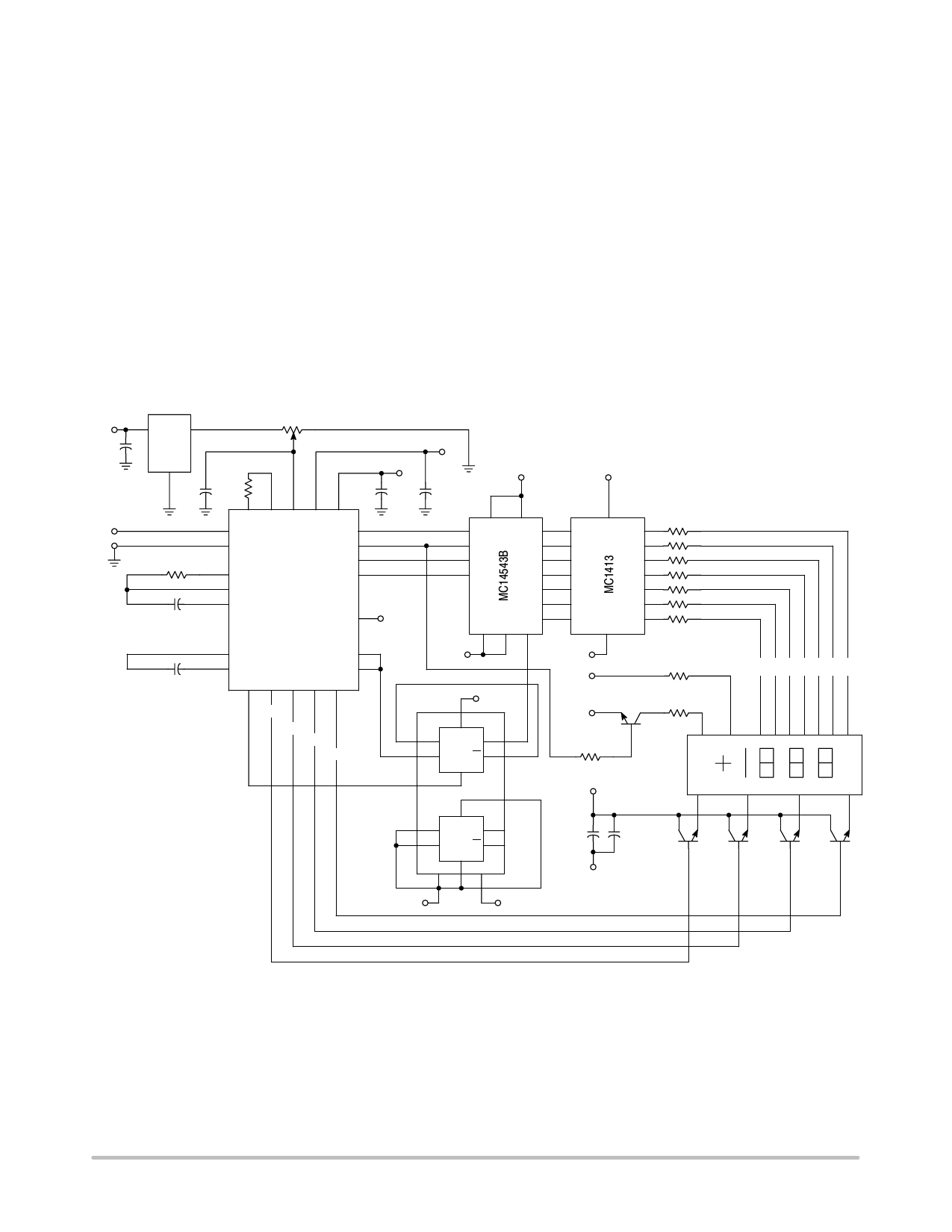
3−1/2−Digit Voltmeter − Common Anode
Displays, Flashing Overrange
An example of a 3−1/2−digit voltmeter using the
MC14433 is shown in the circuit diagram of Figure 8. The
reference voltage for the system uses an MC1403 2.5 V
reference IC. The full scale potentiometer can calibrate for
a full scale of 199.9 mV or 1.999 V. When switching from
2.0 V to 200 mV operation, RI is also changed, as shown on
the diagram.
When using RC equal to 300 kW, the clock frequency for
the system is about 66 kHz. The resulting conversion time
is approximately 250 ms.
When the input is overrange, the display flashes on and
off. The flashing rate is one−half the conversion rate. This
is done by dividing the EOC pulse rate by 2 with 1/2
MC14013B flip−flop and blanking the display using the
blanking input of the MC14543B.
The display uses an LED display with common anode
digit lines driven with an MC14543B decoder and an
MC1413 LED driver. The MC1413 contains 7 Darlington
transistor drivers and resistors to drive the segments of the
display. The digit drive is provided by four MPS−A12
Darlington transistors operating in an emitter−follower
configuration. The MC14543B, MC14013B and LED
displays are referenced to VEE via Pin 13 of the MC14433.
This places the full power supply voltage across the display.
The current for the display may be adjusted by the value of
the segment resistors shown as 150 W in Figure 8.
+5.0 V
0.1 mF
VX
MC1403
20 k
12
3
0.1 mF 300 k
RC
+5.0 V
0.1 mF
−5.0 V
0.1 mF
+5.0 V
RI *
0.1 mF **
11 10 2 12 24
3
23
1
22
21
4
20
5
6
MC14433
13
−5.0 V
4 1 16 9
2
10
3
11
5
12
13
14
15
8 67
+5.0 V
Segment Resistors
150 W (7)
7
10
6
11
5
12
4
13
3
14
2
15
1
16
0.1 mF
7
9
8
14
15 19 18 17 16
DS1
DS2
DS3
DS4
−5.0 V
5.0 V
6
5 D SQ 1
3 C RQ 2
4
8
−5.0 V
−5.0 V
−5.0 V
Minus Sign
200 W
MPS−A12 Plus Sign
110 W
51 k
MC14013B +5.0 V
Common
Anode
LED
Display
f g edc ba
* RI = 470 kW for 2.0 V Range
RI = 27 kW for 200 mV Range
** Mylar Capacitor
9 D S Q 13
11 C R Q 12
7 10 14
−5.0 V
+5.0 V
50 mF
0.1 mF
−5.0 V
MPS−A12
(4)
Figure 8. 3−1/2−Digit Voltmeter
http://onsemi.com
5
Share Link: 