MC1494 データシートの表示(PDF) - ON Semiconductor
部品番号
コンポーネント説明
メーカー
MC1494 Datasheet PDF : 16 Pages
| |||
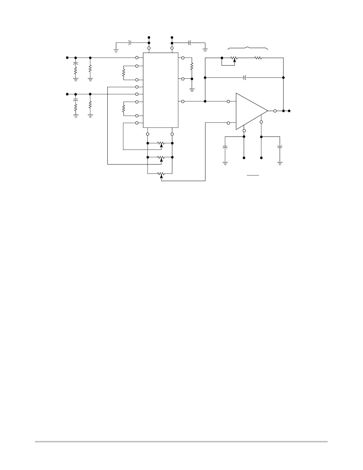
MC1494
VX
10 pF
510
VY
10 pF
510
+15 V
0.1 µF
+15 V
0.1 µF
15
10
+
11
R*
30 k RX 12
5
1
R1
16 k
3
13
-
9
8
+ MC1494
14
+
R*
62 k RY 7
6
--
+
4
2
P1 20 k
RL
50 k
22 k
P4
10 pF
2
-
6
MC1456
VO
3
+
4
7
P2 20 k
0.1 µF
0.1 µF
P3 50 k
*R is not necessary if inputs are DC coupled.
Figure 18. Typical Multiplier Connection
+15 V -15 V
VO = -VX VY
10
-10 V ≤ VX ≤ +10 V
-10 V ≤ VY ≤ +10 V
It should be pointed out that there is nothing magic about
setting the scale factor to 1/10. This is merely a convenient
factor to use if the VX and VY input voltages are expected
to be large, say ±10 V. Obviously with VX = VY = 10 V and
a scale factor of unity, the device could not hope to provide
a 100 V output, so the scale factor is set to 1/10 and provides
an output scaled down by a factor of ten. For many
applications it may be desirable to set K = 1/2 or K = 1 or
even K = 100. This can be accomplished by adjusting RX,
RY and RL appropriately.
The selection of RL is arbitrary and can be chosen after
resistors RX and RY are found. Note in Figure 18 that RY is
62 kΩ while RX is 30 kΩ. The reason for this is that the “Y”
side of the multiplier exhibits a second order nonlinearity
whereas the “X” side exhibits a simple nonlinearity. By
making the RY resistor approximately twice the value of the
RX resistor, the linearity on both the “X” and “Y” sides are
made equal. The selection of the RX and RY resistor values
is dependent upon the expected amplitude of VX and VY
inputs. To maintain a specified linearity, resistors RX and RY
should be selected according to the following equations:
RX ≥ 3 VX (max) in kΩ when VX is in Volts,
RY ≥ 6 VY (max) in kΩ when VY is in Volts.
For example, if the maximum input on the “X” side is ±1.0
V, resistor RX can be selected to be 3.0 kΩ. If the maximum
input on the “Y” side is also ±1.0 V, then resistor RY can be
selected to be 6.0 kΩ (6.2 kΩ nominal value). If a scale factor
of K = 10 is desired, the load resistor is found to be 47 kΩ.
In this example, the multiplier provides a gain of 20 dB.
Operational Amplifier Selection
The operational amplifier connection in Figure 18 is a
simple but extremely accurate current–to–voltage
converter. The output current of the multiplier flows through
the feedback resistor RL to provide a low impedance output
voltage from the op amp. Since the offset current and bias
currents of the op amp will cause errors in the output voltage,
particularly with temperature, one with very low bias and
offset currents is recommended. The MC1456 or MC1741
are excellent choices for this application.
Since the MC1494 is capable of operation at much higher
frequencies than the op amp, the frequency characteristics of
the circuit in Figure 18 will be primarily dependent upon the
operational amplifier.
Stability
The current–to–voltage converter mode is a most
demanding application for an operational amplifier. Loop
gain is at its maximum and the feedback resistor in
conjunction with stray or input capacitance at the multiplier
output adds additional phase shift. It may therefore be
necessary to add (particularly in the case of internally
compensated op amps) a small feedback capacitor to reduce
loop gain at the higher frequencies. A value of 10 pF in
parallel with RL should be adequate to insure stability over
production and temperature variations, etc.
An externally compensated op amp might be employed
using slightly heavier compensation than that recommended
for unity–gain operation.
Offset Adjustment
The noninverting input of the op amp provides a
convenient point to adjust the output offset voltage. By
connecting this point to the wiper arm of a potentiometer
(P3), the output offset voltage can be adjusted to zero (see
Offset and Scale Factor Adjustment Procedure).
http://onsemi.com
7
Share Link: 