NCV33035 データシートの表示(PDF) - ON Semiconductor
部品番号
コンポーネント説明
メーカー
NCV33035 Datasheet PDF : 28 Pages
| |||
MC33035, NCV33035
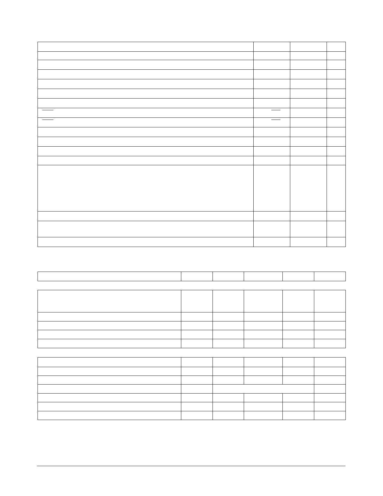
MAXIMUM RATINGS
Rating
Symbol
Value
Unit
Power Supply Voltage
Digital Inputs (Pins 3, 4, 5, 6, 22, 23)
Oscillator Input Current (Source or Sink)
Error Amp Input Voltage Range (Pins 11, 12, Note 1)
Error Amp Output Current (Source or Sink, Note 2)
Current Sense Input Voltage Range (Pins 9, 15)
Fault Output Voltage
Fault Output Sink Current
Top Drive Voltage (Pins 1, 2, 24)
Top Drive Sink Current (Pins 1, 2, 24)
Bottom Drive Supply Voltage (Pin 18)
Bottom Drive Output Current (Source or Sink, Pins 19, 20, 21)
Power Dissipation and Thermal Characteristics
P Suffix, Dual In Line, Case 724
Maximum Power Dissipation @ TA = 85°C
Thermal Resistance, Junction−to−Air
DW Suffix, Surface Mount, Case 751E
Maximum Power Dissipation @ TA = 85°C
Thermal Resistance, Junction−to−Air
Operating Junction Temperature
Operating Ambient Temperature Range (Note 3)
MC33035
NCV33035
VCC
−
IOSC
VIR
IOut
VSense
VCE(Fault)
ISink(Fault)
VCE(top)
ISink(top)
VC
IDRV
40
V
Vref
V
30
mA
− 0.3 to Vref
V
10
mA
−0.3 to 5.0
V
20
V
20
mA
40
V
50
mA
30
V
100
mA
PD
RθJA
PD
RθJA
TJ
TA
867
mW
75
°C/W
650
100
150
−40 to + 85
−40 to +125
mW
°C/W
°C
°C
Storage Temperature Range
Tstg
−65 to +150 °C
Stresses exceeding Maximum Ratings may damage the device. Maximum Ratings are stress ratings only. Functional operation above the
Recommended Operating Conditions is not implied. Extended exposure to stresses above the Recommended Operating Conditions may affect
device reliability.
ELECTRICAL CHARACTERISTICS (VCC = VC = 20 V, RT = 4.7 k, CT = 10 nF, TA = 25°C, unless otherwise noted.)
Characteristic
Symbol
Min
Typ
Max
Unit
REFERENCE SECTION
Reference Output Voltage (Iref = 1.0 mA)
TA = 25°C
(Note 4)
Vref
V
5.9
6.24
6.5
5.82
−
6.57
Line Regulation (VCC = 10 to 30 V, Iref = 1.0 mA)
Load Regulation (Iref = 1.0 to 20 mA)
Output Short Circuit Current (Note 5)
Reference Under Voltage Lockout Threshold
Regline
−
1.5
30
mV
Regload
−
16
30
mV
ISC
40
75
−
mA
Vth
4.0
4.5
5.0
V
ERROR AMPLIFIER
Input Offset Voltage (Note 4)
VIO
−
0.4
10
mV
Input Offset Current (Note 4)
Input Bias Current (Note 4)
Input Common Mode Voltage Range
Open Loop Voltage Gain (VO = 3.0 V, RL = 15 k)
Input Common Mode Rejection Ratio
IIO
−
8.0
500
nA
IIB
−
− 46
−1000
nA
VICR
(0 V to Vref)
V
AVOL
70
80
−
dB
CMRR
55
86
−
dB
Power Supply Rejection Ratio (VCC = VC = 10 to 30 V)
PSRR
65
105
−
dB
1. The input common mode voltage or input signal voltage should not be allowed to go negative by more than 0.3 V.
2. The compliance voltage must not exceed the range of − 0.3 to Vref.
3. NCV33035: Tlow = −40°C, Thigh = 125°C. Guaranteed by design. NCV prefix is for automotive and other applications requiring site and change
control.
4. MC33035: TA = −40°C to +85°C; NCV33035: TA = −40°C to +125°C.
5. Maximum package power dissipation limits must be observed.
http://onsemi.com
3
Share Link: 