MCP1253 データシートの表示(PDF) - Microchip Technology
部品番号
コンポーネント説明
メーカー
MCP1253 Datasheet PDF : 20 Pages
| |||
MCP1252/3
4.2 Power Efficiency
The power efficiency, , is determined by the mode of
operation. In boost mode, the efficiency is approxi-
mately half of a linear regulator. In buck mode, the effi-
ciency is approximately equal to that of a linear
regulator. The following formulas can be used to
approximate the power efficiency with any significant
amount of output current. At light loads, the quiescent
current of the device must be taken into consideration.
EQUATION
BOOST
=
P----O----U----T-
PIN
=
V---V-I--N-O---U----T--2-------I--IO--O--U--U--T--T-
=
V---V-I--N-O---U----T--2-
BUCK
=
P----O----U----T-
PIN
=
-V--V-O---I-U-N---T------I---OI--O-U---U-T--T-
=
V----O----U----T-
VIN
4.3 Shutdown Mode
Driving SHDN low places the MCP1252 or MCP1253 in
a low power shutdown mode. This disables the charge
pump switches, oscillator and control logic, reducing
the quiescent current to 0.1 µA (typical). The PGOOD
output is in a high-impedance state during shutdown.
4.4 PGOOD Output
The PGOOD output is an open-drain output that sinks
current when the regulator output voltage falls below
0.93VOUT (typical). The output voltage can either be
fixed when the selectable output device is chosen
(MCP1252-33X50, MCP1253-33X50) or adjustable
from an external resistive divider when the adjustable
device is chosen (MCP1252-ADJ, MCP1253-ADJ). If
the regulator output voltage falls below 0.93VOUT (typ-
ical) for less than 200 µsec and then recovers, glitch-
immunity circuits prevent the PGOOD signal from tran-
sitioning low. A 10 k to 1 M pull-up resistor from
PGOOD to VOUT may be used to provide a logic output.
Connect PGOOD to GND or leave unconnected if not
used.
4.5 Soft-Start and Short-Circuit
Protection
The MCP1252 and MCP1253 features foldback short-
circuit protection. This circuitry provides an internal
soft-start function by limiting in-rush current during
startup and also limits the output current to 200 mA
(typical) if the output is shorted to GND. The internal
soft-start circuitry requires approximately 300 µsec,
typical with a 5V output, from either initial power-up or
release from shutdown for the output voltage to be in
regulation.
4.6 Thermal Shutdown
The MCP1252 and MCP1253 feature thermal shut-
down with temperature hysteresis. When the die tem-
perature exceeds 160°C, typically, the device shuts
down. When the die cools by 15°C, typically, the device
automatically turns back on. If high die temperature is
caused by output overload and the load is not removed,
the device will turn on and off, resulting in a pulse out-
put.
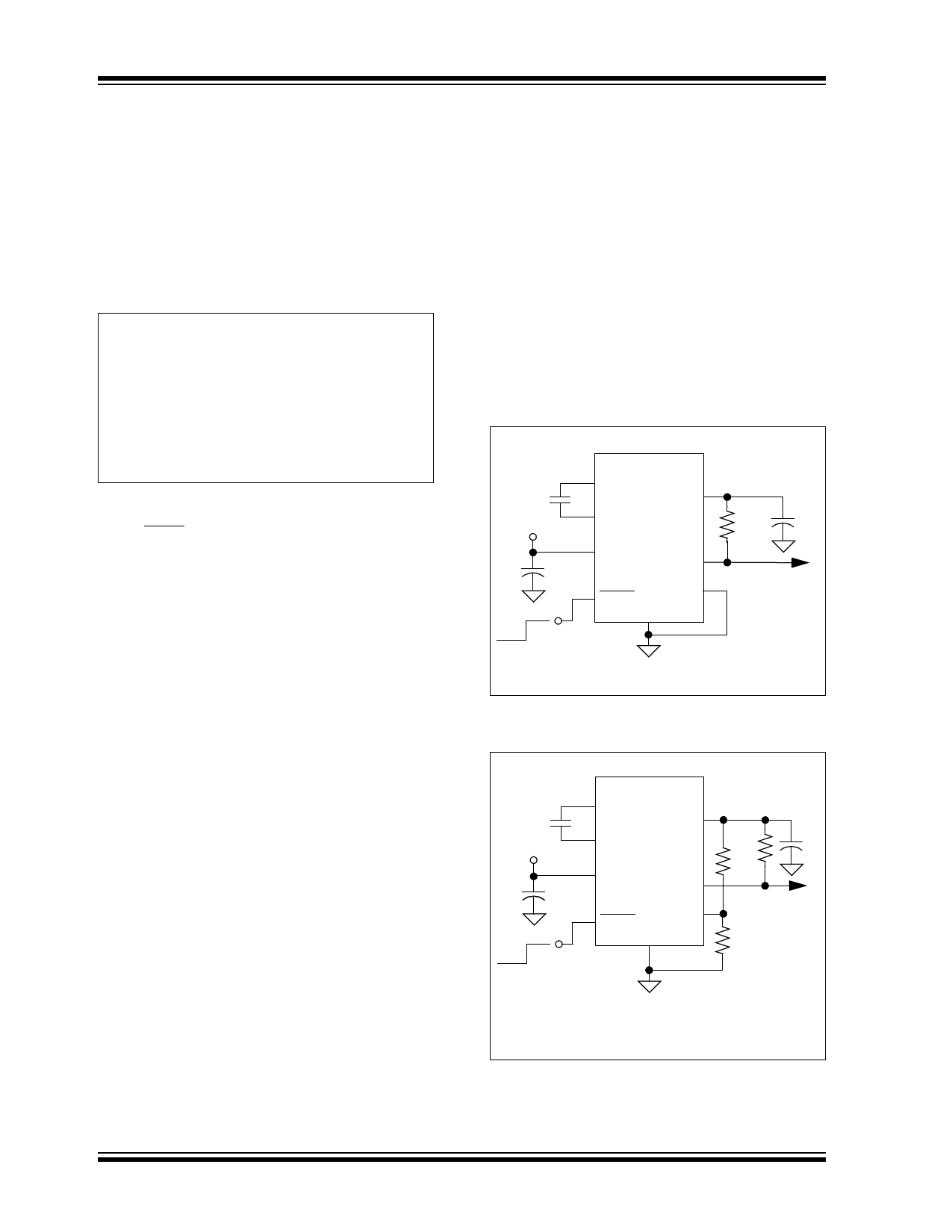
5.0 APPLICATIONS
The MCP1252 and MCP1253 are inductorless, positive
regulated, charge pump DC/DC converters. A typical
circuit configuration for the fixed output version is
depicted in Figure 5-1. The adjustable version is
depicted in Figure 5-2.
SELECTABLE OUTPUT VOLTAGE
CFLY
2.7V to 5.5V
+
CIN
ON
OFF
Shutdown
Control
MCP1252-33X50
6 C+
VOUT 2 +5.0V ±2.5%
5 C-
+
RPU
COUT
3 VIN
PGOOD 1
7 SHDN SELECT 8
GND
4
PGOOD Flag
To PIC®
Microcontroller
CFLY = 1 µF
CIN = 10 µF
COUT = 10 µF
RPU = 100 k
FIGURE 5-1:
Typical Circuit Configuration
for Fixed Output Device.
ADJUSTABLE OUTPUT VOLTAGE
CFLY
2.7V to 5.5V
+
CIN
ON
OFF
Shutdown
Control
MCP1252-ADJ
6 C+
VOUT 2
5 C-
3 VIN
PGOOD 1
7 SHDN
GND
4
FB 8
VOUT = 1.21V (1 + R1/R2)
+4.0V
RPU
+ COUT
R1
PGOOD Flag
To PIC®
Microcontroller
R2
CFLY = 1 µF
CIN = 10 µF
COUT = 10 µF
RPU = 100 k
R1 = 23.2 k
R2 = 10 k
FIGURE 5-2:
Typical Circuit Configuration
for Adjustable Output Device.
DS21752B-page 10
2002-2013 Microchip Technology Inc.
Share Link: 