SC91650 データシートの表示(PDF) - Silan Microelectronics
部品番号
コンポーネント説明
メーカー
SC91650
Silan Microelectronics

SC91650 Datasheet PDF : 30 Pages
| |||
Silan
Semiconductors
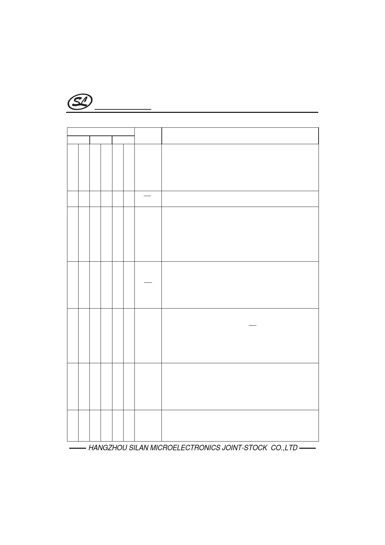
SC91650/1/2 A/B
(continued)
Pin No.
Pin Name
650A/B 651A/B 652A/B
Description
*Handfree input control pin. (SC91650, SC91651)
*Toggle input structure, rising edge trigger.
11
11
*It is used to enable and disable Handfree funtion.
HFI
*With waveshaped by a built-in Schmit trigger, the bounce of input
can be eliminated by external R•C debounce circuit.
* A built-in pull down resistor is 200kΩ typical.
11 HFI
* Toggle input structure with pull up resistance 200kΩ, falling edge
trigger. (SC91652)
* Handfree output pin.
* Inverter output structure (normally ‘low’, active ‘high’).
* When a HFI pin is active, Handfree function will be enabled
12
12
12 HFO (HFO=1) or disable (HFO=0).
* When the Handfree function is enable (HFO=1), after OFF-HOOK
action, it can reset Handfree function and HFO pin return to ‘low’
state.
*Hold line input control pin.
*Toggle input structure, falling edge trigger.
1
1
*It is used to enable and disable Hold line function.
HDI
*With waveshaped by a built-in Schmit trigger, the bounce of input
can be eliminated by extenal R.C debounce circuit.
*A built-in pull up resistor is 200kΩ typically.
*Hold line output pin.
*Inverter output structure, falling edge trigger.
*When a falling edge signal triggered HDI pin, Hold line function will
22
22
HDO be enable (HDO=1) or disabled(HDO=0).
*When the Hold line function is enable (HDO=1), after OFF-HOOK
action or HFO pin is from “low” to “high”, it can reset Hold line
function and HDO pin return to “low” state.
*Keytone output pin for ralid key pad input and memory stored
(SC91652 only).
*CMOS invertor output structure.
22
KT
*It will issue a 1.2kHz, duty cycle 50% signal with duration 30ms.
*To prevent signal interference, while DTMF issue, it will disable
Keytone output except function key.
*Pulse mode mute.
*CMOS inverter output structure.
1 PMUTE
*The output is high state during dialing sequence (pulse mode only),
otherwise this pin is low.
HANGZHOU SILAN MICROELECTRONICS JOINT-STOCK CO.,LTD
REV: 1.0
2001.01.15
10
Share Link: