MGF0904 データシートの表示(PDF) - Mitsumi
部品番号
コンポーネント説明
メーカー
MGF0904 Datasheet PDF : 4 Pages
| |||
< High-power GaAs FET (small signal gain stage) >
MGF0904A
L & S BAND / 0.6W
non - matched
DESCRIPTION
The MGF0904A, GaAs FET with an N-channel schottky
gate, is designed for use in UHF band amplifiers.
FEATURES
High output power
Po=28.0dBm(TYP.) @f=1.65GHz,Pin=15dBm
High power gain
Gp=13.0dB(TYP.) @f=1.65GHz,Pin=15dBm
High power added efficiency
P.A.E =40%(TYP.) @f=1.65GHz,Pin=15dBm
APPLICATION
For UHF Band power amplifiers
QUALITY
GG
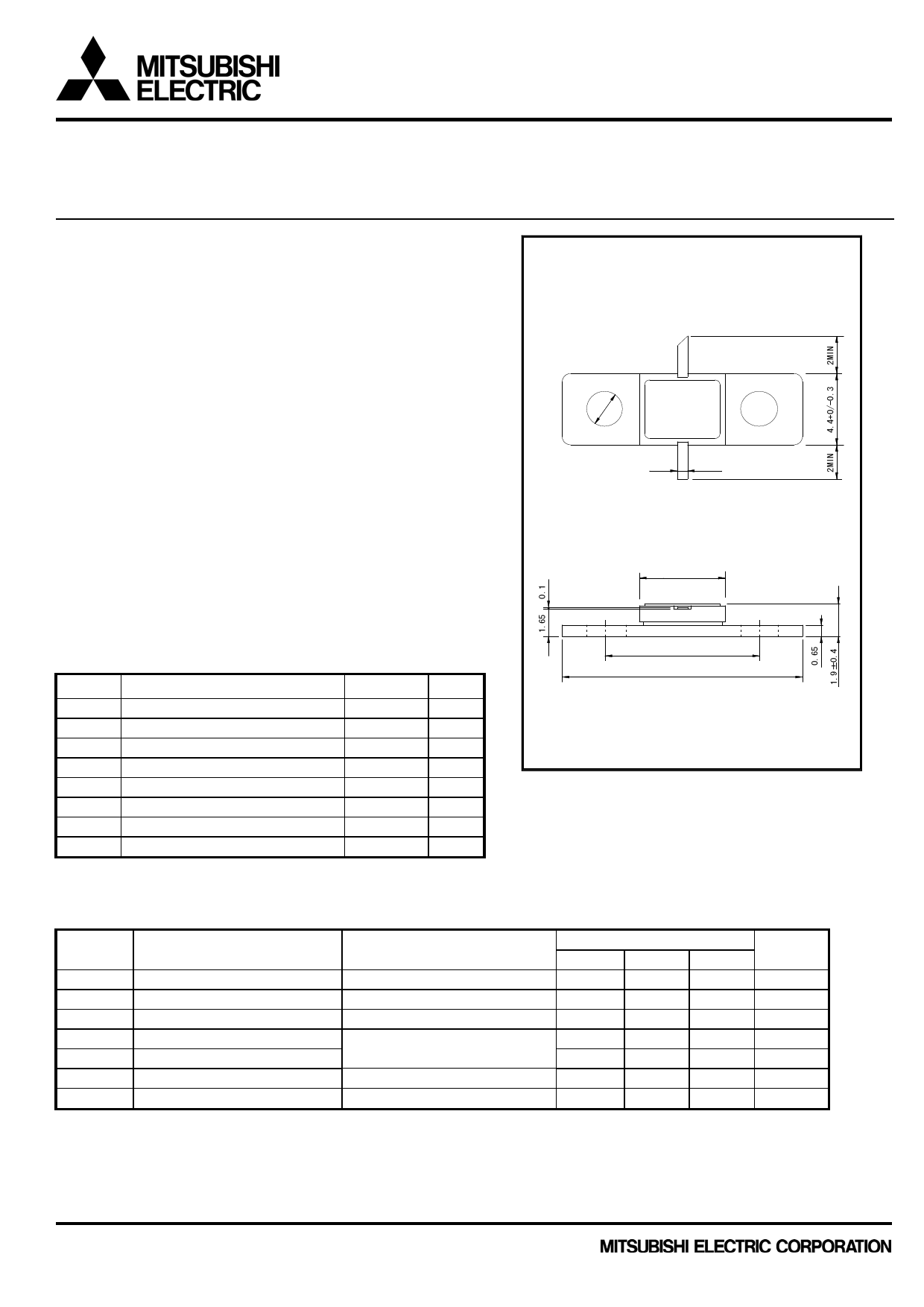
OUTLINE DRAWING
Unit : m illim eters
①
②
φ2.2
②
0.6±0.2
③
RECOMMENDED BIAS CONDITIONS
Vds=8V Ids=200mA Rg=500 Refer to Bias Procedure
Absolute maximum ratings
Symbol
Parameter
VGDO Gate to drain voltage
VGSO Gate to source voltage
ID
Drain current
IGR Reverse gate current
IGF Forward gate current
PT*1 Total power dissipation
Tch Cannel temperature
Tstg Storage temperature
*1:Tc=25C
(Ta=25C)
Ratings
-17
-17
800
-2.5
5.4
3.75
175
-65 to +175
Unit
V
V
mA
mA
mA
W
C
C
Electrical characteristics (Ta=25C)
Symbol
Parameter
Test conditions
IDSS
Saturated drain current
gm
Transconductance
VGS(off) Gate to source cut-off voltage
Po
Output power
P.A.E.
Power added efficiency
Rth(ch-c) *2 Thermal resistance
Rth(ch-a) *3 Thermal resistance
*2 :Channel-case
*3 :Channel-ambient
VDS=3V,VGS=0V
VDS=3V,ID=300mA
VDS=3V,ID=2.5mA
VDS=8V,ID(RF off)=200mA
f=1.65GHz,Pin=15dBm
ΔVf method
ΔVf method
GF-7
5.0
9.0±0.2
14.0
(1) GATE
(2) SOURCE (FLANGE)
(3) DRAIN
Min.
400
120
-1
26
-
-
-
Limits
Typ.
550
200
-3
28
40
-
-
Max.
800
-
-5
-
-
40
100
Unit
mA
mS
V
dBm
%
C/W
C/W
Publication Date : Apr., 2011
1
Share Link: 