MICRF005 データシートの表示(PDF) - Micrel
部品番号
コンポーネント説明
メーカー
MICRF005 Datasheet PDF : 11 Pages
| |||
MICRF005
Application Information
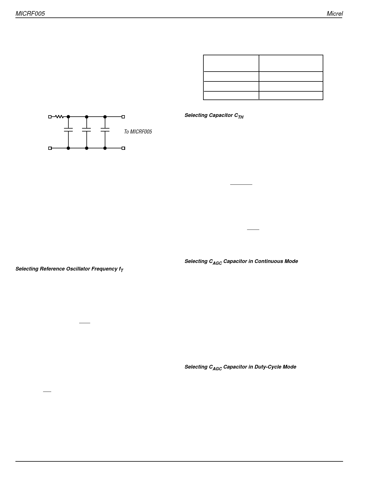
Bypass and Output Capacitors
The bypass and output capacitors connected to VSSBB should
have the shortest possible lead lengths. For best perfor-
mance, connect VSSRF to VSSBB at the power supply only
(that is, keep VSSBB currents from flowing through the VSSRF
return path). VDDRF and VDDBB should be connected directly
together at the IC pins. A 10Ω resistor in series with the supply
line plus three decoupling capacitors is recommended. The
suggested capacitor values are 1nF, 10nF and 100nF.
R1
10R
5V
VDD
C1 C2
To MICRF005
C3
100nF 10nF 1nF
VSS
Figure 8. Supply Bypassing
External Timing Signals
Externally applied signals should be ac-coupled and the
amplitude must be limited to approximately 0.5Vpp.
Optional BandPass Filter
For applications located in high ambient noise environments,
a fixed value band-pass network may be connected between
the ANT pin and VSSRF to provide additional receive selectiv-
ity and input overload protection.
Frequency and Capacitor Selection
Selection of the reference oscillator frequency fT, slicing level
capacitor (CTH), and AGC capacitor (CAGC) are briefly sum-
marized in this section.
Selecting Reference Oscillator Frequency fT
As with any superheterodyne receiver, the difference be-
tween the internal LO (local oscillator) frequency fLO and the
incoming transmit frequency fTX ideally must equal the IF
center frequency. Equation 1 may be used to compute the
appropriate fLO for a given fTX:
(1)
fLO
=
fTX
±
2.496
fTX
915
Frequencies fTX and fLO are in MHz. Note that two values of
fLO exist for any given fTX, distinguished as “high-side mixing”
and “low-side mixing,” and there is generally no preference of
one over the other.
After choosing one of the two acceptable values of fLO, use
Equation 2 to compute the reference oscillator frequency fT:
(2)
fT
=
fLO
64
Equations (1) and (2) can be simplified to:
fT = 63.8258 fTX
Frequency fT is in MHz. Connect a series-mode crystal of
frequency fT to REFOSC on the MICRF005. Four-decimal-
Micrel
place accuracy on the frequency is generally adequate. The
following table identifies fT for some common transmit fre-
quencies when the MICRF005 is operated.
Transmit
Frequency (fTX)
868.35MHz
Reference Oscillator
Frequency (fT)
13.6050MHz
915MHz
14.3359MHz
916.5MHz
14.3594MHz
Table 2. Common Transmitter Frequencies
Selecting Capacitor CTH
The first step in the process is selection of a data-slicing-level
time constant. This selection is strongly dependent on sys-
tem issues including system decode response time and data
code structure (that is, existence of data preamble, etc.). This
issue is covered in more detail in “Application Note 22.”
Source impedance of the CTH pin is given by equation (3),
where fT is in MHz:
(3)
RSC
=
30Ω 14.3359
fT
Assuming that a slicing level time constant τ has been
established, capacitor CTH may be computed using equation
(4).
(4)
CTH
=
τ
RSC
A standard ±20% X7R ceramic capacitor is generally suffi-
cient.
Selecting CAGC Capacitor in Continuous Mode
Selection of CAGC is dictated by minimizing the ripple on the
AGC control voltage by using a sufficiently large capacitor.
Factory experience suggests that CAGC should be in the
vicinity of 0.47µF to 4.7µF. Large capacitor values should be
carefully considered as this determines the time required for
the AGC control voltage to settle from a completely dis-
charged condition. AGC settling time from a completely
discharged (zero-volt) state is given approximately by equa-
tion (5):
(5) ∆t = 1.333CAGC − 0.44
where:
CAGC is in µF, and ∆t is in seconds.
Selecting CAGC Capacitor in Duty-Cycle Mode
Generally, droop of the AGC control voltage during shutdown
should be replenished as quickly as possible after the IC is
“turned-on”. As described in the functional description, for
about [tbd]ms after the IC is turned on, the AGC push-pull
currents are increased to 45 times their normal values.
Consideration should be given to selecting a value for CAGC
and a shutdown time period such that the droop can be
replenished within this [tbd]ms period.
MICRF005
8
October 2001
Share Link: 