MICRF007 гГЗгГЉгВњгВЈгГЉгГИгБЃи°®з§ЇпЉИPDFпЉЙ - Micrel
йГ®еУБзХ™еПЈ
гВ≥гГ≥гГЭгГЉгГНгГ≥гГИи™ђжШО
гГ°гГЉгВЂгГЉ
MICRF007 Datasheet PDF : 13 Pages
| |||
MICRF007
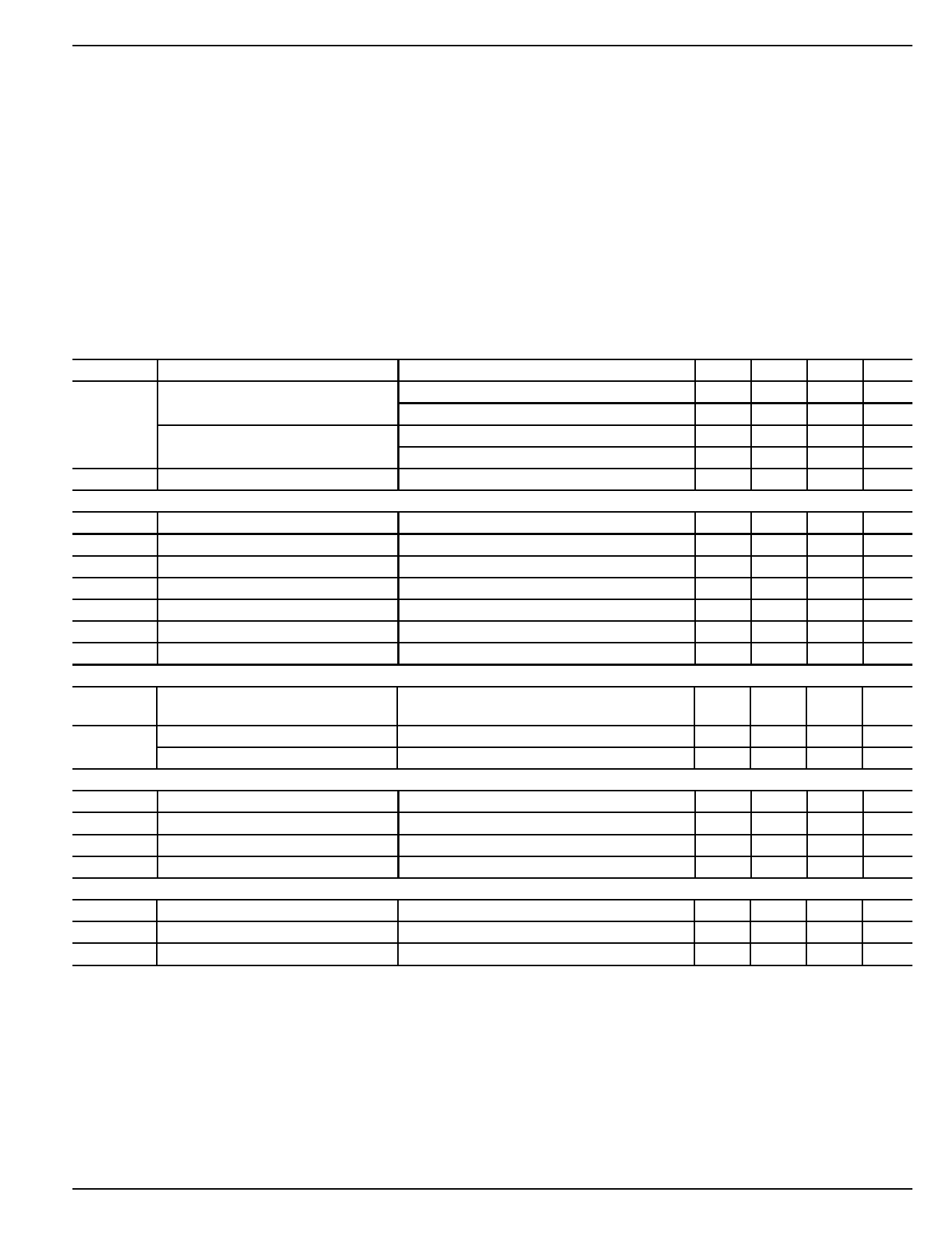
Absolute Maximum Ratings(1)
Supply Voltage (VDD)..................................................... +7V
Input/Output Voltage (VI/O) ...................VSSвАУ0.3 to VDD+0.3
Junction Temperature (TJ) ....................................... +150°C
Storage Temperature Range (TS)............. вАУ65¬∞C to +150¬∞C
Lead Temperature (soldering, 10 sec.).................... +260°C
ESD Rating(3)
Micrel
Operating Ratings(2)
Supply Voltage (VDD)................................. +4.75V to +5.5V
RF Frequency Range ...........................300MHz to 440MHz
Data Duty-Cycle ............................................... 20% to 80%
Reference Oscillator Input range.............. 0.1VPP to 1.5VPP
Ambient Temperature (TA) .......................... вАУ40¬∞C to +85¬∞C
Package Thermal Resistance
8-pin SOIC (ќЄJA) ................................................ 120¬∞C/W
Electrical Characteristics(4)
Power supply: +4.75V вЙ§ VDD вЙ§ 5.5V, VSS = 0V; CAGC = 4.7¬µF, CTH = 0.047¬µF; fT = 6.7458MHz (equivalent of fRF = 433.92MHz); data-
rate = 600bps (Manchester encoded). TA = 25¬∞C, bold values indicate вАУ40¬∞C вЙ§ TA вЙ§ +85¬∞C; current пђВow into device pins is positive;
unless noted.
Symbol
Parameter
Condition
Min Typ Max Units
IOP
Operating Current at 315.0MHz
continuous operation
polled with 10:1 duty cycle
2.3
3.5
mA
230
µA
Operating Current at 433.92MHz
continuous operation
3.8
5.7
mA
polled with 10:1 duty cycle
470
µA
ISTBY
Standby Current
RF Section, IF Section
VSHUT = VDD
0.9
2
µA
Receiver Sensitivity
fRF = 433.92MHz, 1.2kbps
fIF
IF Center Frequency
Note 7
fBW
IF Bandwidth
Notes 6, 7
Maximum Receiver Input
Ref. Impedance = 50ќ©
Spurious Reverse Isolation
ANT pin, Ref. Impedance = 50ќ©(8)
вАУ99
1.18
0.4 0.70
вАУ20
30
dBm
MHz
MHz
dBm
µVrms
AGC Attack to Decay Ratio
AGC Leakage Current
Reference Oscillator(9)
tATTACK √Ј tDECAY
TA = +85°C
10
±50
nA
Reference Oscillator
Stabilization Time
to 1% of пђБnal value
2.5
ms
ZREFOSC
Reference Oscillator Input Impedance
Reference Oscillator Source Current
290
kќ©
5.2
µA
Demodulator
ZCTH
ќФZCTH
IZCTH(leak)
CTH Source Impedance
CTH Source Impedance Variation
CTH Leakage Current
Demodulator Filter Bandwidth
Note 10
TA = +85°C
Note 7
110
kќ©
вАУ15
+15
%
±50
nA
2.5
kHz
Digital/Control Section
IIN(pu)
VIH
VIL
Input Pull-Up Current
Input High Voltage
Input Low Voltage
VSHUT = VSS
VSHUT = VSS
VSHUT = VSS
8
µA
0.8VDD
V
0.2VDD V
February 17, 2005
3
M9999-021705
Share Link: 