MICRF008 データシートの表示(PDF) - Micrel
部品番号
コンポーネント説明
メーカー
MICRF008 Datasheet PDF : 12 Pages
| |||
MICRF008
Micrel
Note 6.
Note 7.
Sensitivity, a commonly specified receiver parameter, provides an indication of the receiver’s input referred noise, generally input thermal
noise. However, it is possible for a more sensitive receiver to exhibit range performance no better than that of a less sensitive receiver if the
background noise is appreciably higher than the thermal noise. Background noise refers to other interfering signals, such as FM radio
stations, pagers, etc.
A better indicator of achievable receiver range performance is usually given by its selectivity, often stated as intermediate frequency (IF) or
radio frequency (RF) bandwidth, depending on receiver topology. Selectivity is a measure of the rejection by the receiver of ambient noise.
More selective receivers will almost invariably provide better range. Only when the receiver selectivity is so high that most of the noise on the
receiver input is actually thermal will the receiver demonstrate sensitivity-limited performance.
Parameter scales linearly proportional with reference oscillator frequency fT. For any reference oscillator frequency other than 3.36 MHz,
compute new parameter value as the ratio:
( ) fREFOSCMHz × parameter value at 3.36MHz
3.36MHz
Note 8. Spurious reverse isolation represents the spurious components which appear on the RF input pin (ANT) measured into 50Ω with an input RF
matching network.
Note 9. Series resistance of the resonator (ceramic or crystal) should be minimized to the extent possible, to ensure oscillation. In case where the
resonator series resistance is too great, the oscillator may oscillate at a diminished peak-to-peak level, or may fail to oscillate entirely. Micrel
recommends that series resistances for ceramic resonators and crystals not exceed 50Ω and 100Ω respectively.
Note 10. Parameter scales inversely proportional with reference oscillator frequency fT. For any reference oscillator frequency other than 3.36 MHz,
compute new parameter value as the ratio:
( ) 3.36MHz × parameter value at 3.36MHz
FREFOSCMHz
CTH source impedance in Table 1 is represented by (sym-
bolic) resistor RSC in the MICRF008 Simplified Block Dia-
gram. The Programmable LPF (Low Pass Filter) is also
illustrated in the MICRF008 Simplified Block Diagram.
SEL0
Programmable LPF
Bandwidth (Hz)
CTH Source
Impedance (Ω)
0
2400
440k
1
4800
220k
Table 1. Nominal Characteristics
Programmable LPF Bandwidth and CTH Source
Impedance
Typical Characteristics
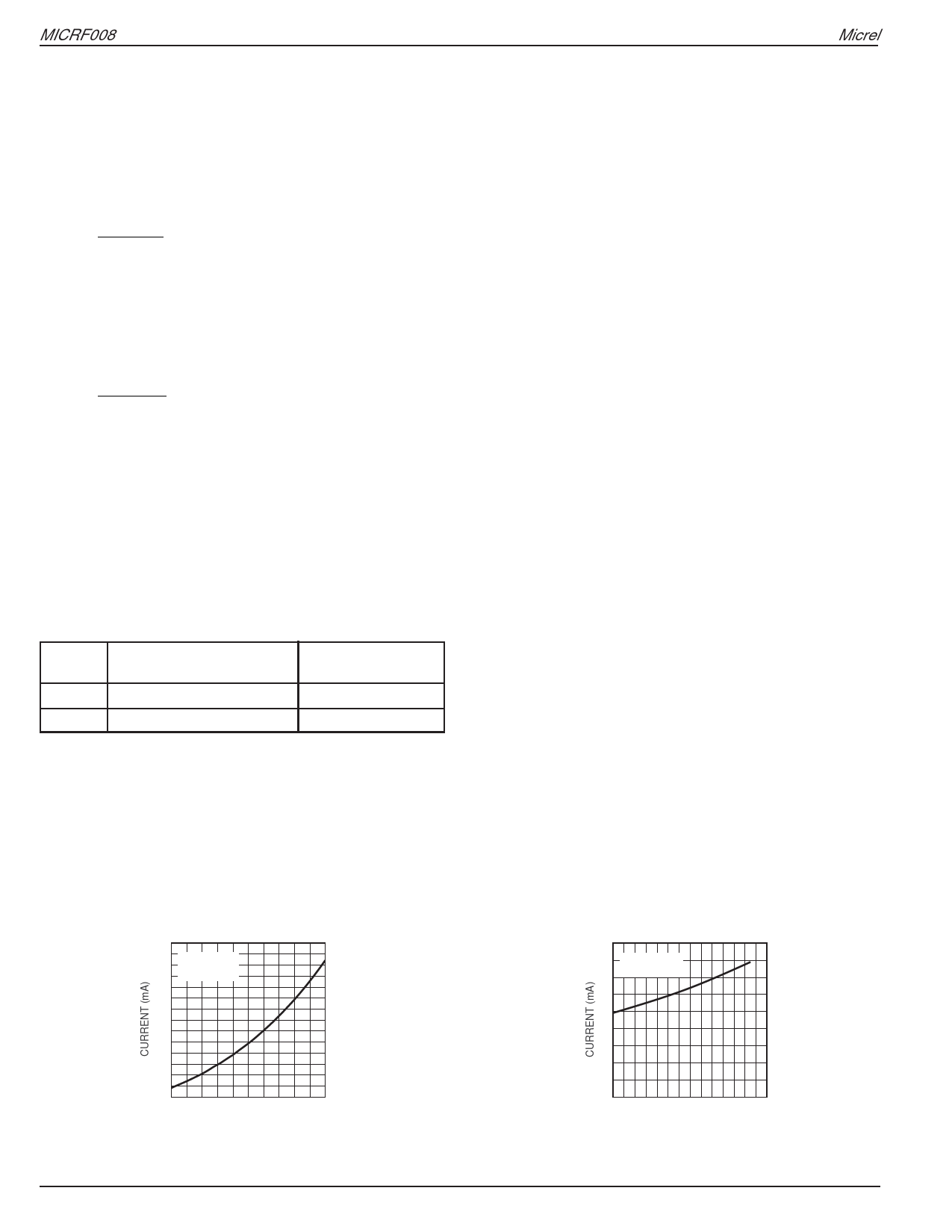
Supply Current
vs. Frequency
18
16 TA = 25°C
VDD = 5V
14
12
10
8
6
4
250 300 350 400 450 500
FREQUENCY (MHz)
MICRF008
4
Supply Current
vs. Temperature
18
16 f = 315MHz
14 VDD = 5V
12
10
8
6
4
2
0
-40 -20 0 20 40 60 80 100
TEMPERATURE (°C)
July 2003
Share Link: 