ML9212 データシートの表示(PDF) - Oki Electric Industry
部品番号
コンポーネント説明
メーカー
ML9212
Oki Electric Industry

ML9212 Datasheet PDF : 17 Pages
| |||
OKI Semiconductor
FEDL9212-01
ML9212
FUNCTIONAL DESCRIPTION
Power-on Reset
When power is turned on, ML9212 is initialized by the internal power-on reset circuit.
The status of the internal circuit after initialization is as follows:
• The contents of the shift registers and latches are set to “0”.
• The digital dimming duty cycle is set to “0”.
• All segment outputs are set to Low level.
• GRID1 outputs are set to Low level.
• GRID2 to 3 outputs are set to High level.
Data Transfer Method
Data can be transferred between the rising edge and the next falling edge of chip select input.
The mode data, segment data and dimming data are written by a serial transfer method. The serial data is input to
the shift register at the rising edge of a shift clock pulse.
The mode data (M0 to M2) must be transferred after the segment data and dimming data succeedingly.
When the chip select input falls, an internal LOAD signal is automatically generated and data is loaded to the
latches.
Function Mode
Function mode is selected by the mode data (M0 to M2). The relation between function mode and mode data is as
follows:
FUNCTION MODE
0
1
2
3
4
OPERATING MODE
Segment Data for GRID1-3 Input
Segment Data for GRID1 Input
Segment Data for GRID2 Input
Segment Data for GRID3 Input
Digital Dimming Data Input
FUNCTION DATA
M0
M1
M2
0
0
0
1
0
0
0
1
0
1
1
0
0
0
1
Segment Data Input [Function Mode: 0 to 3]
• ML9212 receives the segment data when function mode 0 to 3 are selected.
• The same segment data is transferred to the 3 segment data latches corresponding to GRID1 to 3 at the same time
when the function mode 0 is selected.
• The segment data is transferred to only one segment data latch corresponding to the specified GRID when the
function mode is 1, 2 or 3 is selected.
• Segment output (SEG1 to 32) becomes High level (lightning) when the segment data (S1 to S32) is set to “1”.
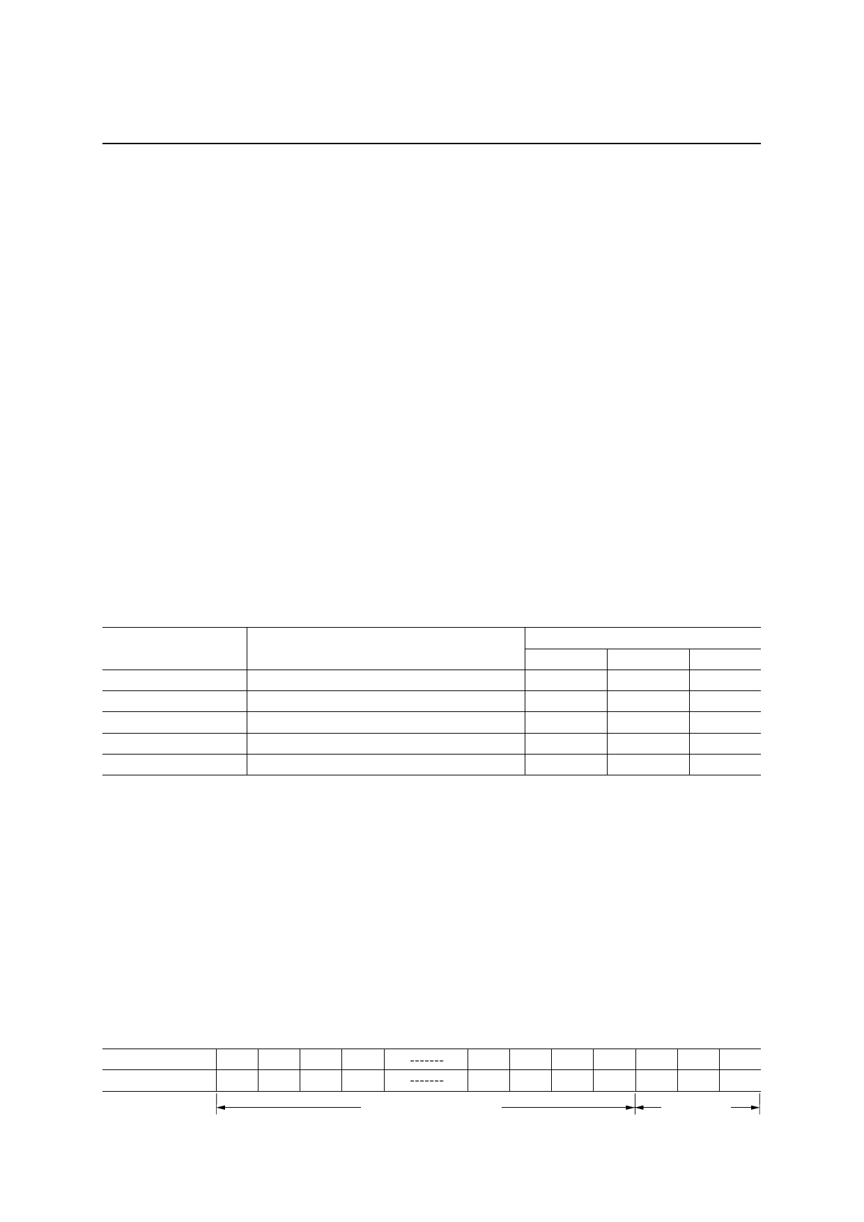
[Data Format]
Input Data
Segment Data
Mode Data
: 35 bits
: 32 bits
: 3 bits
Bit
Input DATA
1
2
3
4
S1 S2 S3 S4
29 30 31 32 33 34 35
S29 S30 S31 S32 M0 M1 M2
Segment Data (32 bits)
Mode Data
(3 bits)
10/17
Share Link: