ML9212 データシートの表示(PDF) - Oki Electric Industry
部品番号
コンポーネント説明
メーカー
ML9212
Oki Electric Industry

ML9212 Datasheet PDF : 17 Pages
| |||
OKI Semiconductor
FEDL9212-01
ML9212
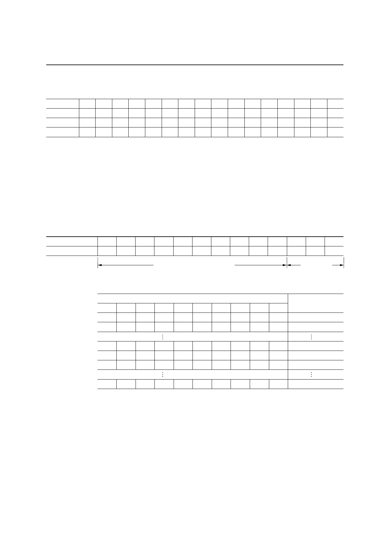
[Bit correspondence between segment output and segment data]
SEG n 1 2 3 4 5 6 7 8 9 10 11 12 13 14 15 16
Segment data S1 S2 S3 S4 S5 S6 S7 S8 S9 S10 S11 S12 S13 S14 S15 S16
SEG n 17 18 19 20 21 22 23 24 25 26 27 28 29 30 31 32
Segment data S17 S18 S19 S20 S21 S22 S23 S24 S25 S26 S27 S28 S29 S30 S31 S32
Digital Dimming Data Input [Function Mode: 4]
• ML9212 receives the digital dimming data when function mode 4 is selected.
• The output duty changes in the range of 0/1024 (0%) to 1016/1024 (99.2%) for each grid.
• The 10-bit digital dimming data is input from LSB.
[Data Format]
Input Data
Digital Dimming Data
Mode Data
: 13 bits
: 10 bits
: 3 bits
Bit
Input DATA
1
2
D1 D2
LSB
3
4
5
6
7
8
D3 D4 D5 D6 D7 D8
Digital Dimming Data (10 bits)
9 10 11 12 13
D9 D10 M0 M1 M2
MSB
Mode Data
(3 bits)
(LSB)
Dimming Data
(MSB)
D1 D2 D3 D4 D5 D6 D7 D8 D9 D10
0
0
0
0
0
0
0
0
0
0
1
0
0
0
0
0
0
0
0
0
Duty Cycle
0/1024
1/1024
1
1
1
0
1
1
1
1
1
1
0
0
0
1
1
1
1
1
1
1
1
0
0
1
1
1
1
1
1
1
1015/1024
1016/1024
1016/1024
1
1
1
1
1
1
1
1
1
1
1016/1024
Master Mode
Master Mode is selected when M/S pin is set at High level. The master mode operation is as follows:
• The input levels of DIM IN, SYNC IN1 and SYNC IN2 are ignored, and these pins should be connected to
L-GND or VDD.
• The pulse width of GRID1 to 3 and SEG1 to 32 are controlled by the internal digital dimming circuit.
• The segment Latch1 to 3 corresponding to GRID1 to 3 are selected by the internal timing generator.
11/17
Share Link: